
DJI D12000iE: Setup, Casters, Handles y Component Map
DJI D12000iE: Setup, Supporting Feet, Casters, Handles y Component Map
El DJI D12000iE Multifunctional Inverter Generator User Guide v1.2 empieza con el assembly de mobility hardware y la identificación de los principales service points. Esta guía convierte esas páginas en un commissioning workflow antes del first start.
Respuesta rápida: retire los 4 original supporting feet, instale los matching supporting feet, monte los casters usando wheel shaft → washer → retaining clip y después instale ambos handles con el supplied M8 hardware. Luego identifique DC module, status LEDs, charging cable, operation panel, air filters, oil dipstick, oil-drain hose, spark arrestor, spark plug y high-pressure oil pipe antes de normal operation.

1. What comes in the box
DJI lists the generator, supporting feet, casters, handles, wheel shafts, washers, retaining clips, bolts/nuts, two wrenches, one engine-oil funnel and one spark-plug socket.
2. Keep the supplied tools with the generator
The oil funnel and spark-plug socket are used later in maintenance. Treat them as generator service tools, not disposable packaging.
3. Remove all four original supporting feet
The setup sequence starts by removing the factory-installed support configuration before caster-compatible feet are fitted.
4. Keep hardware organized
Separate removed bolts/nuts during assembly to avoid mixing original and installation hardware.
5. Install the supporting feet
Align each foot with the generator-frame holes and secure it using the supplied fasteners in the orientation shown by DJI.
6. Install the casters
The illustrated order places the washer on the inner side, then the wheel shaft through the caster/frame, with the retaining clip as the final retention element.
7. Retaining clip is not optional
The clip is the final mechanical retention point for the caster assembly.
8. Install both handles
Align each handle with the frame holes and secure with the supplied M8 hardware.
9. Handles are mobility hardware
Do not assume the handles are approved lifting points unless a separate DJI instruction says so.

10. Post-assembly stability check
Before moving the generator, confirm supporting feet, casters and handles are seated and the frame remains stable.
11. Fuel tank and cap
Identify the fuel service area before first operation.
12. DC module
The D12000iE separates DC-module status from charging-channel and generator/AC status. Know its physical location before troubleshooting.
13. Status LEDs
Three channels support charging, DC-module and generator/AC diagnostics.
14. Charging cable
Inspect cable and connector condition before the first charging session.
15. Operation panel
The panel contains engine-switch, AC-outlet, grounding and control interfaces used during normal operation and diagnostics.
16. Muffler shield and spark arrestor
These exhaust-side service points are separate from intake-air-filter service.
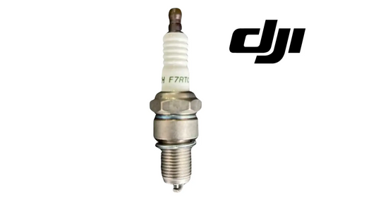
17. Spark plug
Locate the dedicated service point before scheduled maintenance.
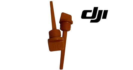
18. Engine-oil dipstick and filler cap
This is the interface used for routine oil-level checks.
19. Engine-oil drain hose
Used for oil replacement and long-term storage preparation.
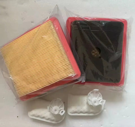
20. Primary and secondary air filters
The D12000iE uses separate filter elements with different service rules.
21. Electronic fuel-injection unit
Identify it as a subsystem; do not select EFI parts simply because the engine has a performance issue.
22. Fan hood
Keep this area free of flammable material and airflow obstruction.
23. High-pressure oil pipe
This service point appears in longer-term storage and maintenance procedures.
24. Oil-level gauge
Know where to inspect before startup.

25. First-use commissioning checklist
- package contents verified;
- four original feet removed;
- new supporting feet installed;
- casters installed and clipped;
- handles installed;
- frame stable;
- service points identified;
- charging cable inspected;
- fuel/oil plan ready;
- pre-operation checklist ready.
26. Receiving photos
Capture package condition, frame, panel, cable and mobility hardware before field deployment.
27. Asset labeling
Add generator model, serial/asset ID and engine/controller build information where tracked. This matters because later DC-controller and filter parts can be build-specific.
28. Build-specific service planning
Do not assume every D12000iE uses identical internal controller/filter parts. Verify exact generator build before ordering.
29. Setup-to-operation handoff
- assemble mobility hardware;
- identify components;
- inspect cable/panel;
- complete fuel/oil pre-operation checks;
- activate/configure as required;
- perform first successful start/charge;
- record baseline.
30. If a caster does not align
Do not force the shaft. Recheck foot orientation, frame alignment and washer placement.
31. If a handle is loose
Resolve the hardware issue before moving the generator.
32. If service tools are missing
Replace them with correct-fit tools before maintenance rather than improvising on spark-plug or oil-service operations.
33. Error común: skip component identification
It makes later troubleshooting slower and less precise.
34. Error común: choose a DC controller before build verification
RATO and Zongshen service paths are separate.
35. Error común: treat handles as confirmed lifting points
The setup guide only establishes them as installed mobility hardware.
36. FAQ
Original feet removed: four. Caster retention: wheel shaft, washer, retaining clip. Handles: supplied M8 hardware. Tools: two wrenches, oil funnel, spark-plug socket. Next step: pre-operation inspection.
Fuente y revisión
Fuente principal: DJI D12000iE Multifunctional Inverter Generator User Guide v1.2, English section, pp. 3–6.