
DJI D12000iE Setup Guide: Supporting Feet, Casters, Handles & Component Map
The DJI D12000iE arrives as a generator package that still needs its mobility hardware assembled before normal field use. This guide turns the setup pages into a visual sequence, then maps the major service points so an operator can move directly from assembly to inspection and maintenance.
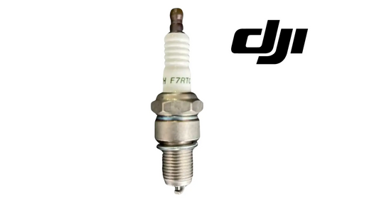
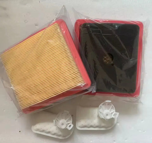
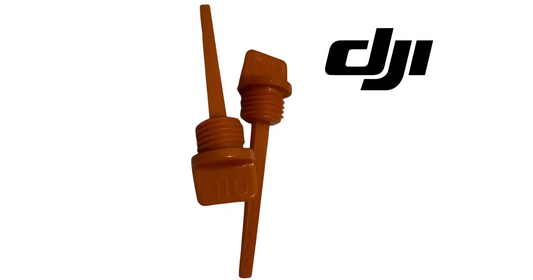
Quick Answer: Remove the four original supporting feet, install the matching supporting feet, fit the casters using the wheel shaft, washer and retaining clip, then install both handles with the supplied M8 hardware. After assembly, identify the DC module, status LEDs, charging cable, operation panel, air filters, oil dipstick, oil drain hose, spark arrestor, spark plug and high-pressure oil pipe before first operation.

What comes in the box
DJI lists the D12000iE generator, two supporting feet, two casters, two handles, matching wheel shafts, washers, retaining clips, bolts and nuts, two wrenches, one engine-oil funnel and one spark-plug socket. Keep the supplied tools with the generator because later maintenance procedures specifically call for the oil funnel and spark-plug socket.

Remove the original supporting feet
DJI instructs the operator to remove all four original supporting feet before installing the caster-compatible feet. Keep the nuts and bolts organized so the new support hardware can be installed without mixing fasteners.
Install the supporting feet
Align the holes in each supporting foot with the generator frame. Insert the bolts through the aligned holes and secure them with nuts. The diagram shows the correct orientation of the support feet beneath the frame.
Install the casters
Place the washer on the inner side of the mounting holes, insert the wheel shaft through the caster and generator frame, then secure the shaft with the retaining clip. The order of the wheel shaft, washer and clip matters because the clip is the final retention element.
Install the handles
Align each handle with the frame holes, insert the mounting bolt and secure with the nut. The handles should be treated as structural mobility hardware, not as a lifting point unless a separate DJI instruction specifically permits it.

Know the service points before first start
The generator overview identifies 22 locations, including the fuel tank and cap, DC module, status LEDs, charging cable, operation panel, muffler shield, spark arrestor, spark plug, engine-oil dipstick, engine-oil drain hose, primary and secondary air filters, electronic fuel-injection unit, fan hood, high-pressure oil pipe and oil-level gauge.
View the complete DJI Agras T50 D12000iE Inverter Generator or browse the DJI D12000iE parts collection.
Parts & Equipment Referenced in This Guide
Shop Related D12000iE Collections
Related D12000iE Tutorials
Source and revision note
Primary source: DJI D12000iE Multifunctional Inverter Generator User Guide v1.2, English section, pp. 3-6.