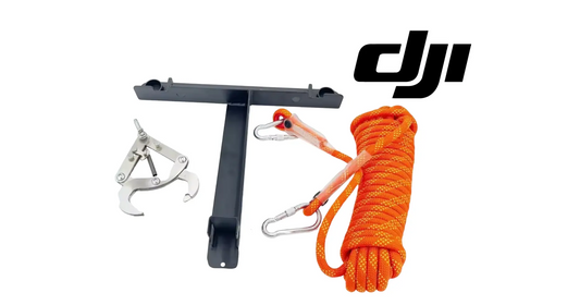

DJI Agras T100 Tutorial: How to Install the DJI T100 Lift System Fuse (FAA Part 137)
Share
🇺🇸 U.S.A. FIRST — Authorized-Dealer Fuse Retrofit, Rope Path, Sensor Wiring & Firmware Commissioning
The DJI Agras T100 lift-system fuse is not a conventional replaceable electrical fuse for circuit protection. It is part of the lifting system’s cable-fuse disconnection and emergency-escape architecture. The retrofit changes the load path around the lifting rope, adds a fuse base and wired fuse module, and requires careful reassembly of the lifting control module, rear-radar connections, three-axis force-sensor wiring, fuse-module wiring, payload connection cable, cable ties, and routing clips. The installation is not complete until the aircraft recognizes the configuration and the required firmware update finishes successfully.
This Ares Acres guide expands DJI’s official “T100 and T70P Lift System Fuse Installation” tutorial into a full technician-facing reference. It preserves the demonstrated order: remove the lifting control module; remove the round retaining ring, nut, connecting hook, and lifting rope; remove the four rope-clamp mounting bolts; install the fuse base with its protrusion facing downward; install the fuse in its housing; route the fuse module and lifting rope through the correct shaft opening; reinstall the retaining nut and R-type pin; secure the control module; reconnect the rear-radar, three-axis force-sensor, fuse-module, and payload wiring; secure the harnesses; install the battery; power on; and complete the prompted firmware update.
Installation-authority warning: DJI’s current T100 Lift System Product Information states that installation can only be completed by an officially authorized dealer and that users should not perform it themselves. This article is therefore an educational, inspection, planning, and authorized-technician reference. It is not a general DIY authorization. The installing dealer must use the current DJI service information, exact kit instructions, approved fastener specifications, approved cable-routing standard, and current firmware for the aircraft being serviced.
Ares Acres supports U.S. DJI Agras operators with aircraft, OEM lift-system components, configuration verification, diagnostics, and practical technical education. Explore the DJI Agras T100, T100 dual-electric lifting system, DJI T100 parts, DJI Agras parts, DJI accessories, the Ares Acres product catalog, or contact Ares Acres before ordering or installing a safety-critical lifting component.
Prefer to watch instead of read? Watch the complete source video before touching the aircraft. The video is the visual reference for part orientation, shaft routing, connector location, cable-tie placement, and wire-clip engagement. Use this written tutorial to establish the authorization boundary, identify documentation conflicts, organize hardware, preserve the sequence, add inspection gates, and document the firmware and return-to-service result.
What You’ll Learn
- What DJI means by the lift-system fuse and emergency-escape function.
- Why the fuse module should not be confused with an ordinary overcurrent fuse.
- Why DJI limits installation to an officially authorized dealer.
- Why the official video title and T100 product-information compatibility statement must be reconciled before installation.
- How the standard and dual-battery T100 lift-system specifications differ.
- Why the exact fuse kit, lifting system, aircraft revision, and firmware must match.
- How to identify the lifting control module before removing hardware.
- Why the Intelligent Flight Battery must be removed before installation.
- How to document all screws, connectors, cable ties, clips, nuts, rings, and pins before disassembly.
- How to remove the lifting control module without pulling a connected harness.
- How the round retaining ring, nut, connecting hook, and lifting rope are removed in sequence.
- How to remove the four rope-clamp mounting bolts while supporting the load-path components.
- Why the fuse-base protrusion must face downward.
- Why no screw torque should be invented when the public tutorial does not publish one.
- How the fuse is inserted into the fuse housing and retained by its nut.
- How the fuse module passes through the correct fuse-base shaft opening.
- How to verify that the keyed protrusion is correctly positioned.
- How to route the lifting rope through the updated assembly.
- How the retaining nut and R-type pin create separate retention checks.
- How to reinstall and secure the lifting control module.
- How to distinguish the rear-radar, three-axis force-sensor, fuse-module, and payload connections.
- Why connector seating and cable routing must be verified independently.
- How cable ties and factory clips prevent chafing, snagging, and movement.
- Why excess cable-tie tail and uncontrolled harness slack can create problems.
- How to inspect the mechanical load path before energizing the aircraft.
- How to inspect the electrical/signal path before installing a battery.
- How to power on in a controlled area and follow the remote-controller firmware prompt.
- Why the battery must remain out until all mechanical and wiring checks pass.
- When tare or weight-sensor calibration is needed under the current lift-system manual.
- How to perform a no-load ground verification without intentionally firing the fuse.
- What conditions require the aircraft to remain out of service.
- What FAA Part 137 does—and does not—authorize for T100 lifting work.
- Why Section 44807, Part 91, operating limitations, and possibly external-load authority may be more relevant to a lifting mission.
Quick Answer: How Is the DJI T100 Lift-System Fuse Installed?
Authorized Dealer Confirms Exact Kit and Aircraft Compatibility → Download Current DJI Video, Product Information, Service Data, and Firmware → Park Aircraft on Level Stable Surface → Remove Intelligent Flight Battery → Control the Work Area and Immobilize the Aircraft → Photograph Lifting Control Module, Fasteners, Connectors, Cable Ties, and Routing → Label Every Connector → Remove All Demonstrated Lifting-Control-Module Screws → Support and Remove the Module Without Pulling Harnesses → Remove the Round Retaining Ring → Remove the Retaining Nut → Remove the Connecting Hook → Withdraw the Lifting Rope → Support the Rope Clamp → Remove the Four Mounting Bolts → Remove the Original Rope Clamp → Position the Fuse Base With Its Protrusion Facing Downward → Start All Four Mounting Bolts → Align and Tighten to Current DJI Dealer Specifications → Insert the Fuse Into the Fuse Housing → Tighten the Fuse-Housing Nut to the Current Approved Specification → Thread the Fuse Module Through the Correct Fuse-Base Shaft Opening → Confirm the Keyed Protrusion Is Fully Positioned → Thread the Lifting Rope Through the Updated Load Path → Install and Secure the Retaining Nut → Install the R-Type Pin Completely → Reinstall and Secure the Lifting Control Module → Reconnect Rear-Radar Cables in the Demonstrated Sequence → Reconnect Three-Axis Force-Sensor Wiring → Reconnect Fuse-Module Wiring → Insert the Payload Connection Cable Into the Correct Board Socket → Secure Fuse Wiring With Cable Ties at the Demonstrated Locations → Plug In the Payload Connection Cable → Snap All Harnesses Into Their Clips → Perform Mechanical, Connector, Routing, and Foreign-Object Inspections → Install the Battery → Power On → Follow the Remote Controller’s Firmware-Upgrade Prompt → Restart as Directed → Clear Every Warning → Verify Configuration and Sensor Readings Unloaded → Calibrate Only if the Current Manual or App Requires It → Complete Approved No-Load Ground Checks → Document and Release the Aircraft Only After Authorized Inspection.
The public video provides the visible sequence, but it does not publish every screw count, fastener size, torque, threadlocker requirement, fuse rating, cable-tie specification, connector-lock detail, software version, or commissioning test. Those values must come from the current dealer/service documentation for the exact aircraft and kit. Do not fill a documentation gap with a guess.
Stop: This Is an Authorized-Dealer Installation
DJI’s product information is unusually direct: installation of the T100 Lift System can only be completed by an officially authorized dealer, and users should not operate it by themselves. That restriction matters because this retrofit affects three safety-critical systems at the same time:
- The mechanical load path — rope, connecting hook, fuse base, housing, shaft, retaining nut, R-type pin, and mounting bolts.
- The sensing and control path — lifting control module, three-axis force sensor, payload connection, and aircraft control board.
- The emergency-release path — fuse module, its wiring, firmware recognition, and the conditions under which the system may be commanded.
A mistake can create a failure that is invisible on the bench but appears under a suspended load. A partially seated connector, reversed keyed part, damaged rope, omitted R-type pin, incorrectly supported cable, or unresolved firmware mismatch can affect load measurement, emergency escape, rear-radar service, or structural retention. For that reason, operators may use this guide to understand the job and audit an installation, but the physical installation should be performed and released by the authorized party required by DJI.
Critical Corrections and Documentation Conflicts
| Topic | Source wording or ambiguity | Current official reference | Required treatment |
|---|---|---|---|
| Who installs it? | The short transcript begins directly with disassembly. | DJI’s T100 Lift System Product Information says installation can only be completed by an officially authorized dealer. | Treat this as authorized-technician training and inspection guidance, not a DIY permission slip. |
| T100 vs. T70P compatibility | The official tutorial title says “T100 and T70P Lift System Fuse Installation.” | The current T100 Lift System Product Information says the T100 system is only compatible with the T100 aircraft. | Do not infer interchangeability. Match the exact kit, aircraft, parts list, firmware, and regional dealer documentation. |
| Meaning of “fuse” | The transcript repeatedly says fuse and fuse module. | DJI’s current T100 specifications call the feature “Cable Fuse Disconnection and Escape.” | Describe it as an emergency cable-disconnection component, not a standard electrical overcurrent fuse. |
| Which lift configuration has the feature? | The video title is broad. | DJI’s current specifications and FAQ explicitly list the fuse/emergency-escape function under the dual-battery lifting system. | Confirm the configuration and retrofit authorization. Do not claim that any standard lift module automatically gains every dual-battery specification. |
| “All screws” | The narration does not give a control-module screw count. | No count is published in the public manual text. | Photograph, map, and account for the screws actually shown on the exact assembly. Do not invent a number. |
| Four mounting bolts | The transcript specifies four bolts at the rope clamp/fuse base. | The video is the visual orientation reference. | Account for exactly four at this interface and use the current dealer torque/specification. |
| Fuse-base orientation | “Ensure the protrusion faces downward.” | Orientation is shown in the official tutorial. | Treat protrusion-down as a hard assembly gate; stop if the base will not seat naturally. |
| “Fuse face shaft hole” | The caption may be an awkward transcription. | The visual shows the fuse module passing through the intended fuse-base/shaft opening. | Use the visual and part geometry. Do not force the module through a similarly shaped opening based on wording alone. |
| Rear-radar “tightening” | The transcript says “tighten the rear radar cables.” | Cables and connectors are seated/secured; they are not tightened like bolts unless their connector design includes a specified lock. | Reconnect each identified radar connector in the demonstrated order and verify its designed lock—do not twist or torque a cable body. |
| Torque and threadlocker | The narration says tighten but gives no numerical values or compound. | The public sources do not publish those installation values. | Use current authorized service data. Do not reuse a torque or threadlocker rule from a different T100 conversion. |
| Firmware | Install battery, power on, follow remote-controller prompts. | The video makes firmware upgrade part of the installation closeout. | Do not release the aircraft with a skipped, interrupted, failed, or unresolved firmware prompt. |
| Weight-sensor calibration | Not stated in this installation transcript. | The current lift manual calls for tare calibration when the aircraft is unloaded but measured weight is not zero. | Verify the unloaded reading and calibrate only when the current app/manual directs it; do not invent an automatic calibration requirement. |
| FAA Part 137 | The requested SEO title references FAA Part 137. | Part 137 concerns qualifying agricultural aircraft operations, not bench installation of a fuse module. | Separate maintenance from flight authority and verify the rules applicable to the specific lifting mission. |
What the Lift-System Fuse Does
DJI’s current T100 specification uses the phrase “Cable Fuse Disconnection and Escape.” The practical purpose is to give a compatible lifting configuration an emergency path for freeing the aircraft when the suspended rope or cargo becomes trapped and the applicable system logic authorizes the response. It should be understood as an aircraft escape feature, not as a substitute for route planning, obstacle avoidance, correct rigging, ground-crew separation, or conservative payload management.
The fuse module is wired because it must communicate with or be controlled through the aircraft’s payload system. The rope passes through the mechanical assembly because the emergency function acts on the load path. Both sides must be correct. A mechanically perfect assembly with an unrecognized fuse harness is incomplete. A recognized electrical module with the rope, nut, pin, or base installed incorrectly is also incomplete.
Do not intentionally command the emergency function as an improvised test. An activation could sever or release the rope, create a dropped-object hazard, consume a service component, or require a defined reset/replacement procedure. Functional testing must follow the current authorized commissioning instructions, with the aircraft unloaded and the drop area controlled whenever a release-capable test is specifically required.
Mechanical Load Path vs. Electrical and Sensor Path
| Path | Primary components in this procedure | Installation objective | Typical hidden failure |
|---|---|---|---|
| Structural attachment | Fuse base, four mounting bolts, control-module housing | Base fully seated, protrusion down, approved fastener retention. | Base appears installed but is keyed incorrectly or pulled into place by bolt force. |
| Rope retention | Lifting rope, connecting hook, shaft opening, retaining nut, R-type pin | Rope follows the demonstrated path and receives both primary and secondary retention. | Nut present but R-type pin omitted or incompletely inserted. |
| Emergency fuse path | Fuse, fuse housing, fuse module, fuse wiring | Correct component orientation, mechanical seating, connector engagement, and firmware recognition. | Module is mechanically present but harness is pinched, loose, or connected to the wrong socket. |
| Load measurement | Three-axis force sensor and its cable | Sensor connection preserved and unloaded reading verified. | Connector looks close but is not locked, producing intermittent or biased load data. |
| Aircraft sensing | Rear-radar cables | Every original connector restored in its correct position and order. | Crossed, partially seated, or strained radar connector after control-module reinstallation. |
| Payload communication | Payload connection cable, control board socket, wire clips | Correct socket, full seating, strain relief, and no chafe. | Cable works during a stationary test but pulls under vibration because it missed a clip. |
| Software configuration | Remote controller, DJI Agras app, aircraft and payload firmware | Prompt completed, versions compatible, no unresolved warning. | Installation released after a skipped or interrupted firmware update. |
Current T100 Lifting-System Specification Reference
DJI’s current T100 support specifications distinguish the standard lifting system from the dual-battery lifting system. The distinction matters because the public specification places the cable-fuse emergency-escape feature under the dual-battery system.
| Specification | Standard lifting system | Dual-battery lifting system |
|---|---|---|
| Aircraft weight in lifting configuration | 65 kg | 90 kg |
| Maximum takeoff weight | 165 kg | 170 kg |
| Module dimensions | 805 × 764 × 669 mm | 805 × 960 × 669 mm |
| Published load capacity | 100 kg | 80 kg |
| Standard lifting-cable length | 10 m | 10 m |
| Recommended cable range | 10–15 m | 10–15 m |
| Published emergency escape mode | Not listed in the current standard-system specification | Cable Fuse Disconnection and Escape |
| Operating temperature | 0–40°C | 0–40°C |
The published capacity includes the weight of ropes and hooks and is measured under DJI’s stated conditions. The DJI Agras app recommends a loading weight based on aircraft state, environment, and task. Never treat 100 kg or 80 kg as a universal field entitlement. Altitude, temperature, wind, battery condition, aircraft configuration, rope behavior, payload shape, and the operator’s approved limitations can reduce the safe value.
Lifting Rope and Hook Requirements
The current T70P/T100 Lift System User Manual publishes the following sling and hook requirements:
| Item | DJI requirement | Installation implication |
|---|---|---|
| Sling length | 10–15 m | Confirm the rope returned through the fuse assembly remains within the approved range. |
| Sling diameter | At least 8 mm | Do not route an undersized substitute merely because it passes through the shaft opening. |
| Sling material | Ultra-high-molecular-weight polyethylene or aramid fiber; high-strength polyester may be used as the inner core | Material compatibility is part of the system, especially where an emergency cable-fuse function is involved. |
| Hook strength | Withstands a pulling force of at least 500 kg | Inspect and retain only the correct hook and connecting hardware. |
| Condition | Secure before each use; replace if visibly worn or cracked | A fuse installation is an opportunity to reject a damaged rope or hook, not reinstall it. |
| Payload attachment | Attach the hook to a reserved knot or ring; do not use the sling itself to tie the payload | The rope is a lifting-system component, not an improvised cargo tie-down. |
Required Materials, Documentation & Work Controls
The source transcript begins with “Prepare required materials.” For an authorized installation, that means more than placing the fuse kit on a bench. The dealer should have:
- the exact DJI lift-system fuse kit matched to the aircraft and lifting configuration;
- the fuse base, fuse housing, fuse module, retaining hardware, and approved wiring supplied for that kit;
- the correct R-type pin and any kit-specific nut, ring, bolts, clips, or cable ties;
- the existing lifting rope and connecting hook, or approved replacements if inspection rejects them;
- the current official installation video and current dealer/service instructions;
- the current T100 Lift System Product Information and Lift System User Manual;
- the current aircraft, payload, and remote-controller firmware package or approved network access;
- correct hand tools and torque-control tools specified by the authorized documentation;
- connector labels, non-damaging markers, fastener trays, and cable-routing photographs;
- approved cable ties and a flush-cutting method that does not leave sharp tails;
- clean lighting, a stable support surface, and a controlled foreign-object area;
- appropriate personal protective equipment for sharp mechanical parts and the shop task;
- a maintenance record identifying the aircraft, lift module, kit, installer, firmware, and final inspection; and
- an out-of-service tag so the battery cannot be installed before mechanical and wiring inspections pass.
The public video does not identify driver sizes, bolt classes, nut torque, screw torque, threadlocker, cable-tie dimensions, or fuse service life. Obtain those details from the current authorized data. Do not borrow the 150 kgf·cm propeller torque or blue-threadlocker instruction from the separate dual-battery conversion tutorial; that specification applies to the components identified in that procedure, not automatically to the fuse-base bolts.
Before You Begin: Aircraft and Shop Safety
Confirm Authorized Scope
Verify that the installing person and location meet DJI’s dealer requirement. Confirm whether the task is a factory-approved retrofit, a service campaign, a lift-system conversion step, or repair of an already approved configuration. Record the controlling document revision.
Remove the Intelligent Flight Battery
DJI’s lift-system manual explicitly says the battery must be removed before installation. Do not treat a powered-off aircraft as de-energized while a DB2160 or other compatible battery remains installed. Keep the battery away from the aircraft until all mechanical and electrical closeout checks are complete.
Control Propeller and Aircraft Movement
Place the T100 on level, stable support with the arms and propellers secured against unintended movement. Follow the authorized shop procedure if propeller removal or another immobilization method is required. Do not work beneath an unsupported aircraft or suspended lift module.
Decontaminate the Work Area
If the aircraft was used for spraying, clean residual liquid from the applicable hoses and surfaces before removing or servicing the payload system. Wear the protective equipment required by the product label and site procedure. Do not bring pesticide residue into an open electronics and connector area.
Preserve Ingress Protection
DJI warns that disassembly and incorrectly secured waterproof covers can reduce protection performance. Keep dirt, liquids, damaged seals, and trapped wires out of every interface. An IPX7 laboratory rating is not permanent and is not permission to pressure-wash an open or freshly serviced module.
Establish a Foreign-Object-Control Zone
Account for every screw, bolt, nut, ring, pin, cable tie, clipping, and tool. The work occurs near mechanical, sensing, and electrical components. A missing fastener can become both a structural defect and a loose object.
Complete DJI T100 Lift-System Fuse Installation Procedure
Phase 1 — Verify Configuration, Document the Aircraft & Remove Power
Step 1 — Identify the Aircraft
Record the aircraft model, serial number, region, current firmware, and current payload configuration. Confirm that the unit being serviced is the exact T100 configuration covered by the authorized work order.
Step 2 — Identify the Lift Module
Record whether the aircraft has the standard or dual-battery lifting configuration, the lift-module identifier, and any prior modification history. Do not decide compatibility from appearance alone.
Step 3 — Identify the Fuse Kit
Match every kit label and part number against the current dealer parts list. Confirm the fuse base, housing, wired fuse module, retaining hardware, R-type pin, mounting hardware, and wiring accessories belong together.
Step 4 — Resolve the T100/T70P Documentation Conflict
If the aircraft is a T70P, stop until current dealer documentation explicitly authorizes the exact kit. The tutorial title includes T70P, while the T100 product information says the T100 system is T100-only. The title alone is not sufficient fitment authority.
Step 5 — Confirm Installation Authority
Document the authorized dealer and technician performing the work. If the work cannot be completed under DJI’s stated installation restriction, do not begin disassembly.
Step 6 — Download Current References
Save or open the current installation video, service instructions, product information, lift-system manual, firmware notes, and any dealer bulletin. Verify revision dates before relying on a previously printed copy.
Step 7 — Record the Pre-Installation Aircraft Status
Before removing the battery, safely record any existing aircraft, radar, payload, force-sensor, or firmware warnings. A pre-existing error should not be attributed automatically to the new fuse installation.
Step 8 — Power Down Normally
Shut down the aircraft and remote controller in the normal sequence. Wait for the system to complete its shutdown before touching the battery.
Step 9 — Remove the Intelligent Flight Battery
Remove the battery completely from the aircraft and place it in the designated safe area. Do not leave it partially inserted or resting on the battery connector.
Step 10 — Tag the Aircraft Out of Service
Place a visible maintenance tag at the battery bay or control point so another technician cannot reinstall a battery during disassembly.
Step 11 — Stabilize the Aircraft
Ensure the landing gear and support surface are stable. Control arm, propeller, and lifting-module movement. The aircraft must not rock while the lifting rope and module are unsupported.
Step 12 — Remove Payload Tension
Confirm that no payload is attached and the lifting rope is completely unloaded. Never disassemble a retaining ring, nut, rope clamp, or fuse base while the rope carries tension.
Step 13 — Clean the Immediate Work Area
Remove loose dirt and crop residue from around the module without driving debris into connectors. Keep liquids and chemical residue away from the opening.
Step 14 — Photograph the Complete Assembly
Capture wide and close views of the lifting control module, screw locations, rope path, hook, round ring, nut, rope clamp, radar cables, force-sensor cable, payload cable, clips, and cable ties.
Step 15 — Build a Fastener and Connector Map
Assign tray positions to each fastener group and labels to each connector. Separate the four rope-clamp bolts from the control-module screws and retaining hardware.
Phase 2 — Remove the Lifting Control Module
Step 16 — Identify Every Control-Module Screw
Compare the exact module with the official video. The narration says to remove all screws but does not publish a universal count. Mark every screw before loosening the first one.
Step 17 — Inspect for Pre-Existing Damage
Look for missing screws, stripped heads, cracked housing, displaced seals, corrosion, chafed cables, loose clips, or evidence that the module has been opened previously. Photograph every abnormality.
Step 18 — Support the Module
Support the control module so it cannot drop or hang from the wiring as the last fasteners are removed. Do not press against a sensor, connector, or cable exit.
Step 19 — Loosen the Screws in a Controlled Pattern
Use the correct driver and keep it square. Loosen progressively so the housing does not twist. If a screw requires abnormal force, stop and follow the approved extraction procedure.
Step 20 — Remove and Map Each Screw
Place each screw in the corresponding tray position. Do not mix lengths or locations. A screw that fits a thread may still be too long for the component beneath it.
Step 21 — Confirm the Fastener Count
Compare the tray with the marked map and starting photographs. Resolve any missing screw before lifting the module away.
Step 22 — Lift the Module Only Far Enough to Inspect Behind It
Separate the module carefully while watching for short harnesses, hidden clips, seals, and connectors. Do not pull it to the end of a cable.
Step 23 — Identify the Rear-Radar Connections
Match the rear-radar connectors to the video and label them individually. Record their positions and routing before disconnecting anything.
Step 24 — Identify the Three-Axis Force-Sensor Connection
Locate and label the force-sensor wiring. This connection supports payload measurement and should never be confused with the radar or fuse connector.
Step 25 — Identify the Payload Connection Cable
Trace the payload cable to the correct board socket and record its connector orientation, locking feature, slack, and clip locations.
Step 26 — Release Connectors by Their Designed Locks
Where disconnection is required by the official sequence, release the connector body or lock—not the wire. Do not twist, pry, or pull on the harness conductors.
Step 27 — Remove the Lifting Control Module
Once every required connector, clip, and fastener is released, remove the module and place it on a clean, protected surface in its installed orientation.
Phase 3 — Remove the Existing Hook, Rope & Rope Clamp
Step 28 — Inspect the Round Retaining Ring
Before removal, photograph its installed orientation and engagement. If it is bent, cracked, corroded, or loose, do not plan to reuse it without approved disposition.
Step 29 — Remove the Round Ring
Unscrew or release the round retaining ring in the sequence shown by DJI. Keep the rope and hook supported so hardware does not drop when retention is reduced.
Step 30 — Inspect and Remove the Retaining Nut
Record the nut orientation, thread engagement, and any locking feature. Remove it with the correct tool while preventing the shaft or rope assembly from rotating uncontrollably.
Step 31 — Remove the Connecting Hook
Withdraw the connecting hook without scoring the shaft opening or dragging the rope across a sharp edge. Place the hook in a protected area for inspection.
Step 32 — Remove the Lifting Rope
Pull the rope through the original path smoothly. Do not cut, kink, twist, contaminate, or use excessive force. Note the direction in which the rope was installed.
Step 33 — Inspect the Entire Accessible Rope Section
Look for glazing, flattening, cuts, abrasion, chemical attack, heat damage, pulled fibers, cracking, contamination, or diameter loss. Replace a visibly worn or cracked sling as DJI directs.
Step 34 — Verify Rope Specification
Confirm the rope meets the current length, diameter, and material requirements. Passing through the old clamp does not prove that a substitute is approved for the fuse system.
Step 35 — Inspect the Connecting Hook
Check for bending, cracks, wear grooves, corrosion, damaged retention, and identification. Confirm the approved strength and kit compatibility.
Step 36 — Locate the Four Rope-Clamp Mounting Bolts
Identify all four bolts shown in the official procedure. Mark their positions and support the rope clamp before loosening them.
Step 37 — Remove the Four Mounting Bolts
Loosen and remove the bolts in a controlled pattern. Place them in four dedicated tray positions and inspect the threads and heads.
Step 38 — Remove the Original Rope Clamp
Lift the clamp away without prying against surrounding wiring, sensor components, or sealing surfaces. Record any shim, locating feature, or orientation visible on the exact assembly.
Step 39 — Inspect the Mounting Interface
Check the four holes, seating surface, and surrounding structure for cracks, deformation, corrosion, contamination, damaged threads, or evidence of movement. Do not cover a structural defect with the new fuse base.
Step 40 — Clean the Interface Under Approved Instructions
Remove only loose dry contamination using the method allowed by current service data. Do not scrape a seal, enlarge a hole, apply unapproved solvent, or remove a coating.
Phase 4 — Install the Fuse Base and Fuse Module
Step 41 — Identify the Fuse-Base Protrusion
Before bringing the part to the aircraft, point to the keyed protrusion identified in the video. Photograph it so the orientation can be audited after seating.
Step 42 — Orient the Protrusion Downward
Position the fuse base with the protrusion facing downward exactly as DJI demonstrates. This is a hard orientation requirement, not a cosmetic preference.
Step 43 — Seat the Fuse Base Without Force
Lower the base onto the mounting interface. It should sit naturally with the holes aligned. If it rocks, binds, or requires bolt force to become flush, stop and find the cause.
Step 44 — Start the First Mounting Bolt
Install the correct bolt by hand far enough to confirm proper thread engagement. Do not tighten it fully.
Step 45 — Start the Remaining Three Bolts
Start all four mounting bolts before applying final torque. Confirm that each turns normally and that the base remains seated with the protrusion down.
Step 46 — Align the Fuse Base
Verify the shaft opening, protrusion, cable path, and surrounding clearances against the official video. The bolts should retain the correct alignment, not create it through force.
Step 47 — Tighten the Four Mounting Bolts
Tighten in the pattern and to the torque required by the current authorized service documentation. Because the public source gives no numerical value, this article does not invent one.
Step 48 — Perform an Independent Bolt Check
Have the installer or a second qualified inspector verify four bolts, correct base orientation, flush seating, no trapped wire, and no damaged thread.
Step 49 — Identify the Fuse and Fuse Housing
Match the fuse component, housing, nut, connector, and orientation to the kit documentation. Reject a damaged, contaminated, previously activated, or unidentified component.
Step 50 — Insert the Fuse Into the Housing
Place the fuse into the housing in the demonstrated direction. Do not force a keyed part or touch a sensitive surface unnecessarily.
Step 51 — Install the Fuse-Housing Nut
Start the nut by hand, verify normal thread engagement, and tighten to the current approved specification. Do not use the wire as a handle or allow the module to twist against its harness.
Step 52 — Route the Fuse Module Through the Intended Shaft Opening
Pass the module through the fuse-base/shaft hole shown in the official video. Protect the connector and wire from sharp edges, twisting, crushing, and abrasion.
Step 53 — Confirm the Protrusion Is Correctly Positioned
Inspect the keyed protrusion again after the module passes through. It must remain in the demonstrated position and the base must remain flush.
Step 54 — Check Fuse-Module Freedom and Clearance
Confirm the module is neither loose nor trapped against a moving or load-bearing surface. Verify the harness can reach its connector along the approved path without tension.
Phase 5 — Reinstall the Lifting Rope, Nut, Pin & Control Module
Step 55 — Orient the Lifting Rope
Use the removal photographs and official video to identify the correct direction. Eliminate twists before feeding it through the updated assembly.
Step 56 — Thread the Rope Through the Fuse Assembly
Pass the rope through the demonstrated path without scraping, compressing, or forcing it. Confirm the rope is not routed outside the intended fuse action area.
Step 57 — Inspect the Rope at Every Contact Point
Look for pinching, sharp-edge contact, abnormal bending radius, trapped fibers, or interference with the fuse wire. The rope should lie naturally through the assembly.
Step 58 — Reinstall the Connecting Hook
Insert the approved hook in its documented orientation and verify that the rope and hook form the intended load path.
Step 59 — Install the Retaining Nut
Start the nut by hand, confirm full and correct engagement, and tighten it to the current dealer specification. Do not guess a torque or rely on “how tight it felt” during removal.
Step 60 — Align the R-Type Pin Hole
Rotate or position the retained assembly only as the authorized instructions allow so the pin hole is fully accessible. Do not partially engage the pin through misaligned holes.
Step 61 — Install the R-Type Pin
Insert the correct R-type pin completely in the demonstrated direction. Verify that the retaining geometry is engaged and the pin cannot migrate out under normal vibration.
Step 62 — Reinstall the Round Ring if Required by the Exact Assembly
Return the round retaining component in the sequence and orientation shown for the kit. If the updated fuse assembly changes the original retention stack, follow the current kit instruction rather than blindly restoring the old order.
Step 63 — Conduct a Mechanical Load-Path Inspection
Trace the path from the mounting structure through the fuse base, fuse housing, shaft, rope, retaining nut, R-type pin, and hook. Confirm nothing is missing, reversed, cross-threaded, loose, pinched, or rubbing.
Step 64 — Inspect the Lifting Control Module Before Reinstallation
Check the housing, seals, connector sockets, wire exits, and mounting points. Do not reinstall a cracked housing or contaminated connector.
Step 65 — Position the Control Module
Bring the module into place without trapping the fuse wire, radar cables, force-sensor cable, or payload cable behind it. Maintain enough access for connector installation.
Step 66 — Start the Control-Module Screws
Install every original screw in its mapped location by hand. Do not swap lengths. Start all screws before final seating so the module can align naturally.
Step 67 — Secure the Control Module
Tighten the screws in the approved pattern and to current service specifications. Verify the housing is flush and no seal or wire is trapped.
Phase 6 — Restore Radar, Force-Sensor, Fuse & Payload Wiring
Step 68 — Reconnect the Rear-Radar Cables in Sequence
Match each labeled connector to its original socket and the video sequence. Align keys, press on the connector body, and engage the designed lock. Do not torque or twist the cable itself.
Step 69 — Verify Every Rear-Radar Connector
Use a visual and light retention check approved for the connector. Confirm no pin is bent, no seal is rolled, and no connector is cross-positioned.
Step 70 — Reconnect the Three-Axis Force-Sensor Wiring
Insert the force-sensor connector into its identified socket in the correct orientation. Support the housing, not the wires, and verify the lock engages.
Step 71 — Reconnect the Fuse-Module Wiring
Route the fuse harness to its assigned connector without crossing a sharp edge or moving component. Seat the connector fully and verify its retention.
Step 72 — Insert the Payload Connection Cable Into the Board
Align the payload connector with the correct control-board socket and insert it evenly. Do not confuse a nearby same-size socket with the documented payload position.
Step 73 — Verify Connector Seating Before Routing
Inspect each connector shoulder and lock. Routing and cable ties cannot compensate for a connector that is only partially inserted.
Step 74 — Route the Fuse Wiring Along the Demonstrated Path
Follow the official video and starting photographs. Preserve separation from the rope, shaft, fastener heads, module edges, and any moving or heat-producing part.
Step 75 — Secure the Fuse Wiring With Approved Cable Ties
Install cable ties at the demonstrated locations and tension them enough to control movement without crushing the harness. Do not place a tie over a connector lock or sensing element.
Step 76 — Trim Cable-Tie Tails Correctly
Use the shop’s approved flush-cutting method. A sharp tail can abrade a neighboring cable, cut a technician, or damage a seal during future service.
Step 77 — Plug In the Payload Connection Cable Completely
Complete any final payload-side connection shown by the video and verify both ends of the cable, not only the end nearest the board.
Step 78 — Snap All Wires Into Their Clips
Place each harness in the correct factory clip. Confirm the clip captures the intended cable without pinching insulation or forcing an unnatural bend.
Step 79 — Check Harness Slack
There should be enough controlled slack for vibration and assembly tolerance but not enough for the wiring to contact the rope, hook, shaft, radar hardware, sharp edge, or fastener.
Step 80 — Compare Routing With the Before-and-After References
Compare the finished layout with the official video and installation photographs. Account for the additional fuse harness without displacing the original radar, sensor, or payload wiring.
Phase 7 — Inspect, Power On, Upgrade Firmware & Commission
Step 81 — Complete a Foreign-Object Inspection
Account for every tool, screw, bolt, nut, ring, pin, tie, label backing, and removed part. Inspect inside and around the module before closing any remaining access.
Step 82 — Complete the Mechanical Checklist
Verify four fuse-base bolts, protrusion down, fuse seated, housing nut secure, rope path correct, hook installed, retaining nut secure, R-type pin fully installed, and module housing secured.
Step 83 — Complete the Electrical and Sensor Checklist
Verify rear-radar, three-axis force-sensor, fuse-module, and payload connectors. Confirm cable ties and clips are correct and no harness is pinched or under tension.
Step 84 — Inspect Seals and Protective Features
Confirm every cover, seal, grommet, and connector protection feature disturbed by the work is correctly restored. Keep the aircraft out of wet service if sealing is uncertain.
Step 85 — Remove the Maintenance Tag Only for Controlled Power-Up
Authorize battery installation only after the mechanical and wiring inspections are signed. The aircraft remains in maintenance status during commissioning.
Step 86 — Install the Intelligent Flight Battery
Install a compatible, serviceable battery under the normal procedure. Keep personnel, tools, and loose material clear of the aircraft and lifting rope.
Step 87 — Power On the Remote Controller
Start the controller, confirm adequate charge and connectivity, and open the DJI Agras app required for the current aircraft.
Step 88 — Power On the Aircraft
Power on from a controlled position with the aircraft unloaded. Be prepared to shut down if smoke, odor, heat, unexpected movement, or a critical warning appears.
Step 89 — Read Every Initial Status Message
Do not dismiss radar, force-sensor, payload, fuse-module, battery, or firmware warnings simply to reach the main screen. Record the exact text and code.
Step 90 — Follow the Firmware-Upgrade Prompt
Use the remote controller and DJI Agras prompts shown in the official tutorial. Maintain stable power and network conditions, and do not disconnect the controller, aircraft, battery, or payload while the update is in progress.
Step 91 — Allow the Update to Complete
Wait for explicit success. A stalled percentage, connection loss, battery warning, or failed component update requires the approved recovery procedure—not repeated random power cycling.
Step 92 — Restart the System as Directed
Complete every instructed restart and allow all modules to initialize. Reopen the device and payload status pages after restart.
Step 93 — Confirm Fuse-System Recognition
Verify that the aircraft and app recognize the installed configuration without unresolved errors. Use the exact status or diagnostic page defined by current service instructions.
Step 94 — Confirm Rear-Radar Status
Ensure the rear-radar connections restored during installation report normally. A fuse installation does not justify returning an aircraft with a new radar warning to service.
Step 95 — Confirm Three-Axis Force-Sensor Status
With the aircraft level and unloaded, verify that the force-sensor data and payload state are plausible and stable.
Step 96 — Check the Unloaded Weight Reading
If the aircraft is unloaded but the measured weight does not equal zero, use the current lift-system manual and app to perform tare calibration. Do not calibrate with the rope pressed against an object or a load attached.
Step 97 — Perform Approved No-Load Ground Functions
Follow the dealer commissioning checklist for payload recognition, sensor status, radar status, and lift-interface response. Keep propellers inactive unless the procedure specifically requires a controlled flight test.
Step 98 — Do Not Intentionally Fire the Fuse Without an Approved Test
A release-capable test can sever or drop the rope and may consume the fuse. Perform it only when the current service procedure explicitly requires it and defines the replacement, containment, and reset process.
Step 99 — Perform an Authorized No-Load Flight Check if Required
Use a closed, clear area, qualified pilot, current operating authority, no payload, conservative altitude, and the exact post-install test profile. Observe sensor readings, warnings, vibration, and rope behavior.
Step 100 — Document and Release the Aircraft
Record the kit identity, component orientation, fastener verification, wiring verification, firmware versions, calibration result, diagnostic results, test result, inspector, and release decision. Do not release the aircraft with any unresolved discrepancy.
Mechanical Closeout Checklist
| Checkpoint | Acceptable result | Reject / hold condition |
|---|---|---|
| Fuse-base compatibility | Exact authorized kit and correct aircraft/lift configuration. | Unresolved T100/T70P or standard/dual-battery mismatch. |
| Fuse-base orientation | Protrusion faces downward and base sits flush. | Protrusion reversed, base rocks, gap present, or bolts used to force alignment. |
| Mounting bolts | Four correct bolts installed to current approved specification. | Missing, mixed, stripped, cross-threaded, or undocumented torque. |
| Fuse and housing | Correct fuse, orientation, housing, nut, and seating. | Unknown component, damaged wire, previously activated part, or loose housing. |
| Rope | Approved length, diameter, material, condition, and routing. | Wear, cracks, cuts, chemical damage, twist, pinch, or unapproved substitute. |
| Hook | Approved hook, undamaged, correctly oriented and retained. | Bending, crack, corrosion, wear, or improvised attachment. |
| Retaining nut | Correct nut, full thread engagement, approved tightening. | Cross-threading, insufficient engagement, wrong nut, or unknown retention. |
| R-type pin | Correct pin fully inserted and positively retained. | Missing, partial, bent, loose, or substituted pin. |
| Control-module housing | Flush, secure, no trapped seal or wire. | Crack, gap, mismatched screw, pinched harness, or compromised protection. |
| Foreign-object control | All tools and hardware accounted for. | Any missing screw, pin, tie fragment, or unidentified loose object. |
Electrical, Sensor & Harness Closeout Checklist
| Connection | Verification | Common failure to catch |
|---|---|---|
| Rear-radar cables | Correct sockets, correct sequence, keys aligned, locks engaged, normal app status. | Crossed connectors, partial seating, pin damage, or cable-body twisting. |
| Three-axis force sensor | Correct socket, lock engaged, stable unloaded reading. | Intermittent connection, trapped wire, or biased weight indication. |
| Fuse-module wiring | Correct connector, full seating, approved routing, protected by ties/clips. | Harness pulled tight, rubbing the rope, or connector mistaken for a similar socket. |
| Payload connection cable | Both ends fully inserted and assigned to correct board port. | One end visually hidden and not fully locked. |
| Cable ties | Correct locations and tension; tails cut flush. | Crushed insulation, sharp tail, tie over a connector lock, or missing support. |
| Wire clips | Every intended cable captured without pinch or excessive bend. | Harness resting beside rather than inside the clip. |
| Clearance | No cable touches rope, shaft, sharp edge, moving part, or bolt head. | Stationary clearance that disappears when the rope moves. |
| Firmware | Upgrade successful; all relevant modules compatible. | Skipped prompt, partial update, version mismatch, or unresolved warning. |
Firmware Upgrade and Commissioning Guidance
The firmware prompt is part of the installation, not an optional convenience. The aircraft must understand the installed lift configuration and communicate correctly with the payload electronics. Before starting:
- use a fully serviceable aircraft battery with adequate margin;
- ensure the remote controller has adequate battery margin;
- use a stable approved internet connection if the package must be downloaded;
- confirm the aircraft and controller remain linked;
- do not begin when the system may be moved, powered down, or disconnected;
- record the starting firmware versions;
- read the update notes and confirm the payload package is included;
- allow the entire update and any component sub-updates to complete;
- restart every device the app identifies; and
- record final versions and all post-update status messages.
If the update fails, preserve the exact code and percentage, confirm power and connection stability, and follow DJI’s recovery guidance. Do not disconnect the fuse module, swap random connectors, downgrade unrelated components, or repeat power cycles without a documented recovery plan.
When Is Tare Calibration Needed?
The current lift-system manual defines a specific trigger: if the aircraft is hovering without cargo but the measured weight does not equal zero, weight-sensor calibration is needed. The manual directs the operator to place the aircraft on level ground, keep it unloaded, ensure the sling is not pressed by another object, and use the tare-calibration control in Operation View.
That means:
- do not calibrate with a payload attached;
- do not let the rope or hook rest against the ground, bench, landing gear, or another object in a way that biases the sensor;
- do not treat calibration as a way to hide a misrouted rope, binding shaft, damaged sensor, or incorrect connector;
- inspect the installation first if the unloaded value is unstable or implausible; and
- record the before-and-after reading when calibration is performed.
Troubleshooting the T100 Lift-System Fuse Installation
| Symptom | Possible categories | Safe diagnostic order |
|---|---|---|
| Fuse base will not sit flush | Wrong orientation, protrusion mispositioned, debris, trapped wire, incompatible kit, damaged mounting surface | Remove the base, confirm protrusion-down orientation, inspect the interface, and verify kit identity. Never pull it flat with bolts. |
| One of four bolts will not start | Misalignment, cross-threading, wrong bolt, damaged thread, incompatible base | Stop, remove bolt load, realign, compare hardware, and use approved thread-repair disposition. |
| Fuse module will not pass through opening | Wrong opening, wrong orientation, connector protection, incompatible module | Return to the video and kit diagram. Do not enlarge the hole or force the connector. |
| Rope will not route naturally | Twist, wrong direction, incorrect fuse orientation, incompatible rope diameter/material, obstruction | Withdraw it, straighten and inspect it, verify specification, and repeat the documented path. |
| Retaining nut will not engage | Misaligned shaft, wrong nut, damaged thread, stack assembled incorrectly | Do not force. Disassemble to the last verified step and inspect threads and component order. |
| R-type pin will not insert fully | Hole misalignment, wrong pin, nut position, burr or damage | Correct the alignment under service data; never fly with a partial or substituted pin. |
| Control module will not sit flush | Harness trapped, seal displaced, wrong screw position, connector interference | Remove the module, inspect the complete perimeter and routing, and reseat without screw force. |
| Rear-radar warning after power-up | Crossed, loose, damaged, or unrecognized rear-radar connection | Power down, remove battery, compare labels and routing, inspect connectors, then retest under the commissioning procedure. |
| Force-sensor error or unstable weight | Loose connection, cable strain, damaged sensor, rope binding, calibration condition | Inspect mechanics and connector first; calibrate only after the installation is verified and conditions meet the manual. |
| Fuse module not recognized | Connector not seated, wrong port, harness damage, incompatible kit, firmware mismatch | Record the message, verify physical connection and compatibility, then complete or recover the official firmware process. |
| Payload module not recognized | Payload cable not seated at one end, wrong board socket, damaged pins, firmware mismatch | Power down and inspect both ends and the exact port before any software reset. |
| Firmware prompt never appears | Already current, module not detected, network/app issue, incorrect configuration | Check device recognition and current versions; do not assume absence of a prompt equals successful installation. |
| Firmware update fails | Low battery, weak connection, interrupted link, version mismatch, module communication fault | Preserve the code, stabilize power/network, and use the approved recovery procedure. |
| New vibration or rattle | Loose base, missing fastener, control-module gap, cable or pin movement | Shut down immediately, remove the battery, and repeat the mechanical/foreign-object inspection. |
| Water or chemical residue found inside | Seal failure, washdown, spray contamination, prior damage | Do not power on. Preserve evidence and obtain authorized inspection/decontamination. |
If the Aircraft Shows Multiple Errors After Installation
Diagnose by dependency rather than clearing messages randomly:
- Record every message and firmware version.
- Power down normally and remove the battery.
- Confirm the control module is seated without a trapped harness.
- Confirm rear-radar connectors using the labels and starting photographs.
- Confirm the three-axis force-sensor connector and cable freedom.
- Confirm the fuse-module connector, route, ties, and clips.
- Confirm both ends of the payload connection cable.
- Inspect connector pins, locks, seals, and port identity.
- Restore power and confirm device recognition.
- Complete or recover the required firmware update.
- Restart and re-read the full status list.
- Escalate with photographs, logs, aircraft ID, kit ID, and exact messages if any error remains.
Common Lift-System Fuse Installation Mistakes
1. Treating the Video as DIY Authorization
The visual procedure does not override DJI’s official-dealer installation restriction.
2. Assuming T100 and T70P Parts Are Automatically Interchangeable
The tutorial title and T100 product information do not align cleanly. Verify the exact kit through current dealer documentation.
3. Confusing the Cable Fuse With an Electrical Protection Fuse
This assembly belongs to the lifting escape/load path. It is not selected or replaced like a generic circuit fuse.
4. Working With the Battery Installed
DJI explicitly requires removal of the Intelligent Flight Battery before lift-system installation.
5. Disassembling an Unsupported Lift Module
The module, rope, and hook must be unloaded and mechanically supported before retention hardware is removed.
6. Failing to Photograph Wiring Before Removal
Radar, force-sensor, fuse, and payload wiring can be confused after the control module is moved.
7. Mixing Control-Module Screws
The public video does not publish one count or length map. Preserve each screw’s original location.
8. Losing the Round Ring, Nut, or R-Type Pin
Small retention components are safety-critical and must remain in separate, labeled tray positions.
9. Pulling a Connector by Its Wires
Release the designed lock and handle the connector body.
10. Forcing the Fuse Base Flat With the Bolts
A correctly oriented, compatible base should seat naturally. Bolt force can hide a protrusion, debris, or compatibility problem.
11. Installing the Protrusion Upward
The official sequence requires the fuse-base protrusion to face downward.
12. Borrowing a Torque From Another T100 Tutorial
Use the service value assigned to this fastener. A propeller or motor-cover specification is not transferable.
13. Applying Unspecified Threadlocker
Use a retaining compound only where the current service data calls for its exact type and amount.
14. Forcing the Fuse Module Through the Wrong Hole
The caption is awkward; use the visual, keyed geometry, and kit drawing.
15. Reinstalling a Worn Rope
Visible wear or cracks require replacement. The open assembly is not a reason to defer it.
16. Using an Undersized or Unapproved Rope
The manual specifies length, diameter, and material. A rope that physically fits may still be incompatible with the load and fuse system.
17. Cross-Threading the Retaining Nut
Start by hand and confirm full engagement before approved tightening.
18. Omitting the R-Type Pin
The nut is not a substitute for the secondary retainer shown by DJI.
19. Partially Inserting the R-Type Pin
Partial insertion can appear acceptable from one viewing angle and still permit migration.
20. “Tightening” a Cable Body
Seat and lock the connector. Do not twist the harness as though it were a threaded fastener.
21. Crossing Rear-Radar Connectors
Label and restore them in the demonstrated sequence; verify normal radar status after power-up.
22. Plugging the Payload Cable Into a Similar Socket
Port identity must be confirmed through the current diagram, not connector size alone.
23. Routing Fuse Wiring Against the Rope
The rope moves and carries load. Maintain the documented separation.
24. Overtightening Cable Ties
Ties should control movement without crushing insulation or stressing connectors.
25. Leaving Sharp Cable-Tie Tails
Flush-cut tails to prevent chafing, sealing damage, and technician injury.
26. Missing a Wire Clip
A harness may pass a stationary test yet move into the rope or hardware during vibration.
27. Installing the Battery Before the Double Inspection
Mechanical and wiring closeout must occur before power is restored.
28. Skipping the Firmware Prompt
The installation is incomplete if the aircraft and payload modules are not software-compatible.
29. Treating a Failed Update as a Reason for Random Power Cycles
Preserve the error and use DJI’s approved recovery sequence.
30. Calibrating Away a Mechanical Problem
An unstable or biased weight reading may come from binding, wiring, or damage. Inspect first.
31. Function-Testing the Fuse Over People or Equipment
A release-capable test requires an approved method and controlled drop zone.
32. Loading the Aircraft Before a No-Load Verification
Configuration, sensors, radar, firmware, and rope path must be verified unloaded first.
33. Assuming Part 137 Automatically Covers Lifting Cargo
Part 137 applies to qualifying agricultural aircraft activity; the actual lifting mission and external-load authority must be evaluated separately.
Recommended Authorized-Installation Record
| Record field | Information to capture |
|---|---|
| Aircraft | Model, serial number, registration, region, total hours/cycles as applicable. |
| Lift configuration | Standard or dual battery, module identifier, prior modifications. |
| Fuse kit | Kit name, part numbers, lot/serial data, compatibility authorization. |
| Installer | Authorized dealer, technician, date, facility, work-order number. |
| Source documents | Video, service instruction, manual, product information, revision/date. |
| Pre-existing condition | Warnings, damage, rope/hook condition, photographs, firmware versions. |
| Power isolation | Battery removed and aircraft tagged before disassembly. |
| Hardware accountability | Control-module screw map; four base bolts; ring, nut, R-type pin. |
| Base orientation | Protrusion facing downward, flush seating, photograph, inspector initials. |
| Approved tightening | Fastener identification, service value, tool ID/calibration status where required. |
| Rope and hook | Length, diameter, material, condition, hook rating/condition, routing. |
| Connector verification | Rear radar, three-axis force sensor, fuse module, payload cable. |
| Harness routing | Cable-tie locations, clip engagement, clearances, after photograph. |
| Firmware | Starting versions, update package, result, final versions, warnings. |
| Calibration | Unloaded reading; tare calibration only if required; before/after result. |
| Commissioning | Ground checks, no-load test, authorized flight test if required, fuse-test disposition. |
| Release | Inspector, unresolved items, final airworthy/operational disposition. |
Post-Installation Inspection Before Every Lift Operation
Installation approval is not permanent proof of condition. Before each use:
- inspect the fuse base, housing, rope path, retaining nut, and R-type pin;
- confirm the lifting rope and hook are secure and free of visible wear or cracks;
- check the fuse harness, payload cable, and accessible clips for movement or chafing;
- confirm the lifting control module is secure and sealed;
- review the aircraft status list and clear no unexplained radar, sensor, payload, or fuse warning;
- confirm the unloaded weight reading is plausible;
- use only the recommended rope length and approved hook arrangement;
- secure the cargo to a dedicated knot or ring and never use the lifting rope itself as the tie-down;
- respect the app’s recommended load rather than the marketing maximum;
- keep personnel at least 6 m from the aircraft and never directly beneath it; and
- confirm the route is free of obstacles because the lift operation cannot automatically bypass them.
Pair this installation reference with the T100 lifting-interface and transportation tutorial, the T100/T50 pre-flight safety tutorial, and the T100 dual-battery lift-system installation guide.
FAA Part 137 and T100 Lifting: Important U.S. Clarification
Installing the fuse module is maintenance; it is not an FAA Part 137 operation. Part 137 is an operating rule for qualifying agricultural aircraft activities. It does not certify an installer, approve the fuse kit, establish torque, authorize a firmware configuration, or release the aircraft after maintenance.
The T100 also exceeds Part 107’s under-55-pound scope. The FAA’s Section 44807 guidance explains that civil operation of an unmanned aircraft above that limit can require exemption authority, supporting manuals, emergency procedures, checklists, maintenance information, training, flight history, and safety analysis. The FAA’s Part 91 waiver guidance identifies pathways for civil unmanned aircraft weighing 55 pounds or more.
A lifting mission is not automatically agricultural dispensing merely because a DJI Agras aircraft performs it. Transporting saplings, fruit, fertilizer bags, tools, building materials, or other cargo on an external line may require analysis of the operator’s exemption, aircraft registration, COA, operating limitations, purpose, compensation, hazardous-material status, and external-load authority. The FAA separately regulates rotorcraft external-load operations under Part 133; whether and how that framework applies to a specific unmanned operation should be confirmed with the FAA/FSDO and the operator’s approved documents rather than assumed from this article.
If the T100 is being used to dispense economic poisons, seeds, fertilizers, or other materials in a qualifying agricultural aircraft operation, Part 137 and the operator’s agricultural-aircraft certificate may apply alongside Part 91, Section 44807 relief, registration, COA, and operating limitations. If the mission is lifting or transporting an external load rather than dispensing it, verify the actual authority for that mission. Never treat “FAA 137” in a title as a blanket permission for every T100 use.
Related Ares Acres T100 Tutorials
- DJI Agras T100 Lift System Dual-Battery Installation — airframe conversion, power distribution, motor-cover replacement, torque, routing, and firmware.
- DJI T100 Transportation and Lifting-Interface Calibration — task planning, load display, calibration, swing control, and field workflow.
- DJI T100/T50 Pre-Flight Safety Tutorial — aircraft, payload, battery, controller, site, and status checks.
- DJI Agras Remote Operation View — interface orientation and aircraft-status monitoring.
- How to Use the DJI Agras Relay — communications setup, firmware, placement, and field verification.
- DJI Agras Battery Fleet Management — firmware compatibility, cycle records, BMS service, and fleet controls.
- Browse All DJI Agriculture Tutorials.
FAQ: DJI Agras T100 Lift-System Fuse Installation
What is the DJI T100 lift-system fuse?
It is part of the cable-fuse disconnection and emergency-escape system used by a compatible lifting configuration. It is not a generic electrical overcurrent fuse.
What does the emergency-escape function do?
It provides a designed path for freeing the aircraft from a trapped or entangled lifting line under the approved system logic and operating procedure.
Can the aircraft owner install it?
DJI’s T100 Lift System Product Information says installation can only be completed by an officially authorized dealer and users should not perform it themselves.
Why publish a tutorial if the dealer must install it?
The guide helps operators understand the configuration, evaluate a dealer’s work, prepare the aircraft, inspect the finished system, recognize errors, and maintain accurate records. It also supports trained authorized technicians.
Does the official video cover both T100 and T70P?
The official video title names both. However, DJI’s current T100 product information says the T100 Lift System is only compatible with T100. The exact T70P kit and dealer authorization must therefore be confirmed separately.
Can I assume the T100 fuse kit fits a T70P?
No. Resolve the documentation conflict through current parts data, serial/revision checks, firmware compatibility, and authorized dealer support.
Which T100 lifting configuration lists the fuse feature?
DJI’s current specification page lists “Cable Fuse Disconnection and Escape” under the dual-battery lifting system and not under the standard-system specification.
Does adding the fuse automatically convert the standard module into the complete dual-battery system?
No. The dual-battery conversion changes additional aircraft power and structural components. Use the exact approved configuration and do not infer capabilities from one added part.
What is the standard T100 lifting capacity?
DJI currently publishes 100 kg for the standard lifting system, subject to its stated conditions and the app’s recommended load.
What is the dual-battery T100 lifting capacity?
DJI currently publishes 80 kg for the dual-battery lifting system. The configuration trades some load capacity for two-battery endurance and the listed emergency-escape feature.
Does the published load include the rope and hook?
Yes. DJI’s specification note says the load figure includes the ropes and hooks.
What lifting-rope length does DJI recommend?
DJI recommends 10–15 m and supplies a 10 m rope in the standard configuration.
What rope diameter is required?
The current lift-system manual specifies at least 8 mm.
What rope materials are permitted?
DJI specifies ultra-high-molecular-weight polyethylene or aramid fiber, with high-strength polyester permitted as the inner core.
What hook strength is required?
The manual requires a hook that withstands a pulling force of at least 500 kg.
Can I use the lifting rope to tie around the cargo?
No. DJI says to attach the hook to a reserved knot or ring on the payload and not to use the sling itself as the tie-down.
Must the aircraft battery be removed?
Yes. DJI’s lift-system manual explicitly requires removal of the Intelligent Flight Battery before installation.
How many screws hold the lifting control module?
The transcript says to remove all of them but does not publish a universal count. The authorized technician should map the screws on the exact module and preserve every location.
How many bolts hold the rope clamp or fuse base?
The source procedure identifies four mounting bolts at that interface.
Which direction does the fuse-base protrusion face?
Downward. Confirm that orientation before starting the four bolts and again after final seating.
What torque should be used on the four bolts?
The public video and user manual do not publish the number. The authorized installer must use the current dealer/service specification for the exact hardware.
Should blue threadlocker be used?
Only if the current fuse-kit service data requires the exact compound and amount. Do not transfer the blue-threadlocker instruction from a different T100 conversion procedure.
What is the “fuse face shaft hole” mentioned in the transcript?
It appears to be an awkward caption for the intended fuse-base/shaft opening shown in the video. Use the visual orientation and current kit diagram rather than forcing the module based on wording alone.
Why is the R-type pin important?
It provides a positive secondary-retention check at the rope/hook shaft assembly. The nut alone does not replace the pin shown in the procedure.
Can I substitute a different cotter or clip?
Not without approved parts data. Use the exact retainer assigned to the assembly.
What wiring is reconnected?
The transcript identifies rear-radar cables, three-axis force-sensor wiring, fuse-module wiring, and the payload connection cable.
Do radar cables get “tightened”?
Connectors should be seated and their designed locks secured. Do not twist or torque the cable body. Follow any connector-specific lock instruction in the service documentation.
Why are cable ties required?
They control fuse-harness movement and preserve clearance. They must be placed and tensioned correctly so they do not crush insulation or load a connector.
Why must wires be snapped into clips?
The clips provide routing and strain control during vibration and rope movement. A loose harness can chafe, snag, or pull on a connector.
Can the battery be installed before the control module is fully secured?
No. Finish the mechanical, connector, harness, seal, and foreign-object inspections before restoring power.
Is a firmware update required?
The official installation sequence directs the technician to power on and follow the remote controller’s firmware-upgrade prompts. Treat that as part of the closeout.
What if no firmware prompt appears?
Confirm module recognition and current versions. The absence of a prompt may mean the system is current, but it can also mean the fuse or payload module is not detected.
What if the firmware update fails?
Record the exact error and percentage, stabilize battery/network/link conditions, and use DJI’s approved recovery procedure. Do not release the aircraft.
Does the weight sensor need calibration after installation?
Verify the unloaded reading. The current manual requires tare calibration when the aircraft is unloaded but the measured weight does not equal zero.
Can calibration fix an unstable weight reading?
Not necessarily. Inspect the rope path, force-sensor connector, cable strain, binding, and mechanical installation before calibrating.
Should the emergency fuse be activated during testing?
Only if the current authorized commissioning procedure explicitly requires it and defines the safe drop zone, consumable replacement, reset, and documentation.
Can the aircraft carry a payload immediately after the update?
No. It first needs mechanical closeout, sensor and radar verification, an unloaded reading check, and approved no-load commissioning.
Does FAA Part 137 regulate installation?
No. Installation is a maintenance/configuration action. Part 137 concerns qualifying agricultural aircraft operations.
Does Part 137 automatically authorize lifting cargo?
No. A lifting mission may fall outside agricultural dispensing and may require separate analysis under the operator’s Part 91/Section 44807 authority, operating limitations, COA, and external-load requirements.
Can the T100 fly under Part 107?
The T100’s published weights exceed Part 107’s under-55-pound scope. U.S. civil operations must use the authority appropriate to the aircraft and mission.
Could Part 133 matter?
Part 133 regulates rotorcraft external-load operations. Whether and how it applies to a particular unmanned lifting mission should be confirmed with the FAA/FSDO and the operator’s approved exemption and operating documents.
What should be documented after installation?
Record aircraft and kit identity, authorization, hardware count, base orientation, approved tightening data, rope/hook condition, connector and routing checks, firmware versions, calibration, commissioning, warnings, inspector, and release status.
Final Takeaway
The DJI T100 lift-system fuse installation is a compact procedure with unusually high consequences. The visible actions—remove the lifting control module, remove the hook and rope, replace the four-bolt rope clamp with the correctly oriented fuse base, install the fuse and housing, restore the rope and secondary retainer, reconnect four wiring groups, secure the harnesses, and update firmware—join the aircraft’s structure, sensors, payload communications, radar connections, and emergency-escape system in one job.
The strongest installation standard is not “the parts fit.” It is: exact kit compatibility is documented; an authorized dealer performs the work; the battery remains removed until closeout; the protrusion faces downward; all four base bolts use current service specifications; the rope, hook, nut, and R-type pin form the correct load path; every connector is positively seated; every harness is clipped and protected; firmware finishes successfully; unloaded sensor readings are plausible; no radar or payload warning remains; and the aircraft passes the authorized commissioning process before any load is attached.
Complementary DJI T100 Lift-System Equipment & Parts
- DJI Agras T100 Dual-Electric Lifting System — the dual-battery heavy-lift configuration associated with the published cable-fuse emergency-escape feature.
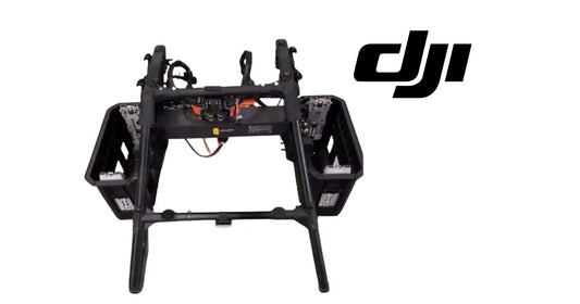
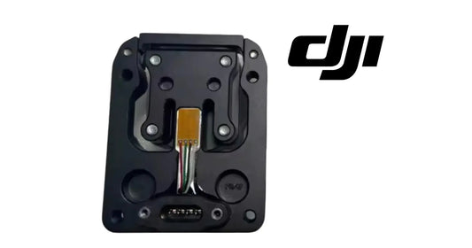
- DJI Agras T100 OEM Payload Lifting Control Module — the control assembly accessed during the demonstrated fuse installation.
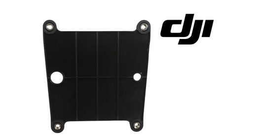
- DJI Agras T100 OEM Lift-System Control Board Bracket — OEM structural support for the lift-system control-board area.
- DJI Agras T100 OEM Lifting Connecting Bracket — an OEM structural lifting-system component that should be matched by part identity and aircraft revision.
- DJI Agras T100 Parts — OEM T100 structural, electrical, sensing, power, and payload components.
What Is Ares Acres?
Ares Acres is a U.S.-based DJI Agras dealer supporting commercial applicators, farms, agricultural-drone technicians, and fleet operators with genuine DJI equipment, parts identification, diagnostic guidance, long-form operator education, and field-ready support.
Need T100 Lift-System Parts or Authorized Configuration Support?
Browse the DJI Agras T100, T100 dual-electric lifting system, T100 parts collection, or the full Ares Acres product catalog. For compatibility verification, fuse-kit sourcing, lift-module identification, or help coordinating authorized installation, contact Ares Acres before the aircraft is disassembled.
Educational, service, and regulatory note: This article expands DJI’s official tutorial for training, inspection, and maintenance planning. DJI states that T100 Lift System installation must be completed by an officially authorized dealer. Always use the current service information for the exact aircraft, lift module, fuse kit, firmware, and region. Do not substitute this article for DJI dealer data, an airworthiness determination, FAA authorization, the operator’s exemption and operating limitations, load-rigging qualification, or legal advice.