
DJI Agras T100 Tutorial: How to Install the Lift System Dual Battery Version
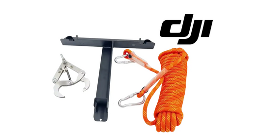
Share
DJI Agras T100 Tutorial: How to Install the Lift System Dual Battery Version- FAA Part 107, FAA 137
🇺🇸 U.S.A. FIRST — DJI Agras T100 Dual-Battery Lifting-System Conversion, Power Distribution & Motor-Cover Installation
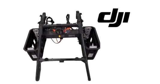
The DJI Agras T100 Lift System Dual Battery Version changes more than the number of batteries carried by the aircraft. The conversion introduces a new front top shell and power-distribution-board fixing bracket, changes how the lifting flight platform connects to the T100 airframe, requires deliberate routing for both dual-battery and single-battery operation, and replaces the upper cover on every motor before the aircraft is returned to service.
The propeller work is especially exacting. Each affected assembly must be removed with a 13 mm wrench, the new motor upper cover must be installed with four M2.5 screws, and the propeller must be rebuilt with the lower spacer protrusion facing upward and the upper spacer protrusion facing downward. DJI’s tutorial then calls for blue adhesive on the motor shaft and a recommended tightening torque of 150 kgf·cm, approximately 14.7 N·m, before the process is repeated for the remaining seven motor covers.
This Ares Acres tutorial expands DJI’s installation video into a complete technician-facing workflow. It preserves the demonstrated sequence while adding power-isolation boundaries, hardware organization, connector verification, single-battery storage logic, spacer-orientation checks, torque discipline, firmware-upgrade precautions, troubleshooting, and U.S. regulatory context for large T100 lifting operations.
Ares Acres supports DJI Agras operators with aircraft, OEM replacement parts, diagnostics, technical education, and field-operation resources. For T100 equipment and support, explore the DJI Agras T100, DJI T100 Parts, DJI Agras Parts, DJI Accessories, the Ares Acres Product Catalog, or contact Ares Acres.
Prefer to watch instead of read? The video above demonstrates DJI’s installation sequence. Use this written guide to track the top-shell conversion, lifting-platform connection, power-distribution routing, eight motor-cover installations, propeller stack orientation, final torque, and firmware update without losing the relationship between individual steps.
What You’ll Learn
- What is included in the DJI T100 Lift System Dual Battery Version conversion.
- How the standard and dual-battery lifting systems differ in DJI’s published specifications.
- Why all batteries must be removed before mechanical or electrical installation.
- How to remove the power-distribution-board dustproof cover.
- How to remove and replace the front top shell.
- How to install the power-distribution-board fixing bracket.
- How to position the lifting flight platform.
- How to lock the middle-frame latch.
- How to connect and latch the payload cable interface.
- How to insert the power-distribution connector until it clicks.
- How the connector is stored for single-battery operation.
- Why both locating pins must be fully aligned on the landing-gear crossbeam.
- How to move power-distribution-board wiring behind both battery sliders.
- How to remove a propeller with a 13 mm wrench.
- How to preserve each propeller, clamp, spacer, and fastener position.
- How to remove an original motor upper cover with an M2.5 screwdriver.
- How to install the new motor upper cover.
- Which direction each propeller-spacer protrusion must face.
- Where DJI’s blue adhesive or threadlocker enters the procedure.
- How to apply the recommended 150 kgf·cm propeller-fastener torque.
- Why the full process must be repeated across all eight motor covers.
- How to perform an eight-position verification audit.
- How to power on and complete the required firmware upgrade.
- How FAA Part 107, Section 44807, Part 91, and Part 137 may relate to T100 lifting operations.
Quick Answer: How Do You Install the DJI T100 Lift System Dual Battery Version?
Power Off T100 → Remove Every Battery → Inventory Dual-Battery Lift Kit → Remove Four Power-Distribution-Board Dustproof-Cover Screws → Remove Dustproof Cover → Remove Front Top-Shell Screws → Remove Original Front Top Shell → Install New Front Top Shell → Install Power-Distribution-Board Fixing Bracket → Place Flight Platform Onto Dual-Battery Lift System → Lock Middle-Frame Latch → Connect Payload Cable and Snap It Into Its Latch → Insert Power-Distribution Connector Until It Clicks → Configure Connector Storage and Wiring for Single-Battery Clearance → Use 13 mm Wrench to Remove Two Propeller Fasteners → Remove Clamp, Upper Spacer, and Propeller → Use M2.5 Driver to Remove Four Motor-Cover Screws → Replace Motor Upper Cover → Reinstall Four Screws → Install Lower Spacer With Protrusion Up → Install Propeller → Install Upper Spacer With Protrusion Down → Install Propeller Clamp → Apply DJI-Specified Blue Adhesive → Tighten to 150 kgf·cm → Repeat for Seven Remaining Motor Covers → Audit All Eight Positions → Insert Battery → Power On → Complete Firmware Upgrade in Remote Controller App.
The four most consequential errors are energizing the aircraft during open electrical work, failing to seat the power-distribution connector until it clicks, reversing either propeller spacer, and tightening a propeller fastener without the specified blue adhesive and verified 150 kgf·cm torque.
Standard vs. Dual-Battery DJI T100 Lifting Systems
DJI publishes different ratings for the standard lifting system and the dual-battery lifting system. The dual-battery configuration should not be described as an automatic payload-capacity increase.
| DJI T100 specification | Standard lifting system | Dual-battery lifting system |
|---|---|---|
| Listed system dimensions | 805 × 764 × 669 mm | 805 × 960 × 669 mm |
| Listed load capacity | 100 kg | 80 kg |
| Standard lifting-cable length | 10 m | 10 m |
| Recommended cable length | 10–15 m | 10–15 m |
| Listed operating temperature | 0–40°C | 0–40°C |
| Emergency escape mode | Refer to current configuration documentation | Cable fuse disconnection and escape |
| Aircraft weight in DJI specifications | 65 kg with lifting system | 90 kg with dual-battery lifting system |
| Listed maximum takeoff weight for lifting | 165 kg | 170 kg |
These figures describe published system limits under DJI’s stated conditions. The DJI Agriculture app can recommend a lower loading weight based on aircraft condition, environment, altitude, temperature, battery state, and task. Never exceed the lowest applicable aircraft, system, authorization, manual, site, or operating limit. Review the current official DJI Agras T100 specifications before configuring a mission.
Why the Dual-Battery Installation Includes Motor Upper Covers
The installation is not limited to attaching a second battery path. DJI’s procedure replaces the front top shell, adds a power-distribution-board fixing bracket, revises cable storage near both battery sliders, and installs a new upper cover on every motor.
The motor-cover conversion must be treated as an eight-position aircraft-wide modification. Completing only one or several covers and then powering the aircraft creates an inconsistent configuration that has not followed the demonstrated procedure.
The propeller must be removed to access each upper cover, which means every motor position also becomes a propeller-installation task. Spacer direction, propeller position, clamp placement, blue adhesive, and final torque all become flight-critical verification points.
Installation Components & Required Tools
Components Identified in the DJI Procedure
- DJI Lift System Dual Battery Version;
- replacement front top shell;
- power-distribution-board fixing bracket;
- new motor upper covers for all eight positions;
- associated lifting flight platform and payload connection;
- required mounting hardware; and
- the approved blue adhesive or threadlocker specified by DJI.
Confirm the exact contents against the kit packing list. Do not begin installation if one motor cover, bracket, fastener, locating feature, or connector component is missing.
Tools Identified in the DJI Procedure
- 13 mm wrench for propeller fasteners;
- torque-capable 13 mm tool for final 150 kgf·cm tightening;
- M2.5 screwdriver for motor upper-cover screws; and
- the correct driver for power-distribution-board cover and top-shell screws.
Recommended Work-Control Materials
- eight labeled motor-position trays or bags;
- labels for propeller position and orientation;
- clean protective coverings;
- calibrated torque tool capable of approximately 14.7 N·m;
- DJI-specified blue adhesive or threadlocker;
- non-permanent marker or position labels;
- inspection light;
- lint-free cleaning materials; and
- the latest DJI installation and service documentation.
Do not substitute generic glue for the specified blue product. “Blue adhesive” in the source procedure should be treated as DJI’s specified removable thread-retention material and applied only at the location and quantity shown in the current instructions.
Before You Begin: Power Isolation & Propeller Safety
Aircraft State
- Land and stabilize the aircraft on a level service surface.
- Power the aircraft off completely.
- Remove every installed flight battery.
- Keep batteries away from the work area until all eight propeller assemblies are complete.
- Do not perform open-connector or propeller service with a battery installed.
- Prevent another technician from energizing the aircraft during the job.
Propeller Area
- Treat each propeller as position-specific unless DJI explicitly states otherwise.
- Mark the motor position and propeller orientation before removal.
- Keep hands and tools clear of propeller edges.
- Support the propeller so removing the fasteners does not bend or strike it.
- Never rotate a powered motor during installation.
- Inspect every propeller for cracks, delamination, deformation, impact marks, and contaminated mating surfaces.
Hardware Control
Use a separate labeled tray for each motor position. Keep its:
- two 13 mm fasteners;
- propeller clamp;
- upper spacer;
- propeller;
- lower spacer;
- four M2.5 cover screws; and
- original motor cover
together until that position is rebuilt and independently verified.
U.S. Regulatory Context: Part 107, Section 44807, Part 91 & Part 137
Installing the lift system does not determine the legal authority for the eventual flight. Aircraft weight and mission purpose matter.
Part 107 Does Not Independently Cover a T100 at or Above 55 Pounds
The FAA’s Part 107 guidance applies to small UAS weighing less than 55 pounds at takeoff. DJI’s published T100 weights are well above that threshold before a lifting load is added.
A Part 107 Remote Pilot Certificate may remain a pilot-qualification element in a specific exemption or authorization, but the aircraft is not converted into a Part 107 small UAS merely because the pilot holds that certificate.
Large T100 Operations Can Require Section 44807 and Part 91 Authority
The FAA explains that operators seeking to fly an aircraft above the Part 107 weight threshold may need authority under 49 U.S.C. §44807, together with the applicable exemption, registration, Part 91 conditions, COA, and operating limitations.
The operator must verify that the specific T100 configuration, dual-battery system, maximum weight, lifting mission, and aircraft identification are covered by the actual authorization.
Part 137 Depends on the Mission
Part 137 governs covered agricultural aircraft operations, particularly dispensing economic poisons or other agricultural materials and related operations within its definitions. Installing a lift system does not automatically make every lifting or delivery mission a Part 137 operation.
A lifting mission may instead implicate other large-UAS, external-load, cargo, hazardous-material, airspace, or operating requirements depending on what is carried, why it is carried, whether property is transported for compensation, and how the flight is conducted. The operator should obtain mission-specific regulatory guidance rather than treating “Part 107” or “Part 137” as a universal label.
This tutorial covers hardware installation, not legal authorization.
Step 1 — Unpack and Inventory the Dual-Battery Lift System
Take out the DJI Lift System Dual Battery Version and inventory its supplied components.
The source procedure specifically calls out:
- the replacement front top shell; and
- the power-distribution-board fixing bracket.
Also verify that the required new motor upper covers and related hardware are present for all eight positions before aircraft disassembly begins.
Compare every component with the packing list. Stop if there is shipping damage, a bent bracket, cracked shell, missing cover, damaged connector, or incomplete hardware.
Step 2 — Confirm the Aircraft Is Powered Off and Remove All Batteries
Before removing covers or touching the power-distribution board, power the T100 off and remove all installed batteries.
Physical battery removal is the electrical-isolation boundary. Do not rely solely on the power button while the power-distribution connector, payload cable, top shell, and propeller assemblies are being serviced.
Step 3 — Remove the Four Dustproof-Cover Screws
Unscrew the four screws securing the power-distribution-board dustproof cover on the T100 airframe.
Support the cover while removing the final screw. Place all four fasteners in a labeled tray and inspect them for damage or contamination.
Do not allow a screwdriver to slip into the power-distribution board or wiring area.
Step 4 — Remove the Power-Distribution-Board Dustproof Cover
Lift away the dustproof cover.
Keep the exposed power-distribution area clean and dry. Do not place loose screws, tools, threadlocker, or debris on the board. Inspect visible connectors and wiring for damage before continuing.
The cover must be reinstalled or replaced as required by the completed configuration before the aircraft returns to service.
Step 5 — Remove the Front Top-Shell Screws
Unscrew the fasteners securing the original front top shell.
Record screw locations if lengths or types differ. Do not assume every shell screw is interchangeable. Keep the shell hardware separate from the four dustproof-cover screws and all propeller hardware.
Step 6 — Remove the Original Front Top Shell
Remove the front top shell carefully.
Lift it without snagging wiring, connectors, brackets, or airframe features beneath it. Observe how the original shell seats and where its edges, tabs, and fasteners align.
Inspect the exposed area for:
- pinched wiring;
- damaged insulation;
- loose hardware;
- chemical contamination;
- dust or debris;
- cracked mounting points; or
- signs of heat or arcing.
Correct any abnormal condition before installing the replacement shell.
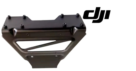
Step 7 — Install the New Front Top Shell
Reinstall the new front top shell in the reverse or specified assembly sequence.
Seat the shell evenly. All tabs, edges, holes, and interfaces should align without force. Do not use the screws to pull a misaligned shell into place.
Start the fasteners in their correct positions, then tighten them using DJI’s sequence and specified torque if provided. Confirm no wire is trapped beneath the shell.
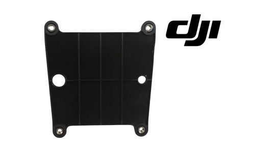
Step 8 — Install the Power-Distribution-Board Fixing Bracket
Install the supplied power-distribution-board fixing bracket.
The bracket should sit in the intended orientation and support the connector arrangement without loading the board or wiring. Confirm:
- mounting holes align;
- bracket is fully seated;
- no wire lies underneath it;
- connector movement is not obstructed; and
- the dustproof-cover area remains compatible with the final assembly.
Step 9 — Position the Flight Platform on the Dual-Battery Lift System
Place the flight platform onto the DJI Lift System Dual Battery Version.
Support the platform during positioning. Do not allow its weight to hang from the payload cable or power-distribution connector.
Align the platform with the middle frame before closing any latch. A platform that is not fully seated can place abnormal load on the latch and cable interfaces.
Step 10 — Lock the Middle-Frame Latch
Close and lock the middle-frame latch.
Verify that it reaches the fully locked position and physically retains the platform. Do not accept a partially closed latch or one that requires excessive force because the platform is misaligned.
Step 11 — Connect the Payload Cable Interface
Connect the payload cable interface.
Align the connector and engage it fully. Handle the connector body rather than pulling or pushing on the wires.
Inspect for:
- bent or recessed pins;
- damaged seals;
- chemical residue;
- broken latch features; or
- wire strain.
Step 12 — Snap the Payload Cable Into Its Latch
Secure the payload cable interface in the dedicated latch.
The cable should be supported and restrained without being crushed, sharply bent, or held under tension. Confirm the latch is fully closed.
Step 13 — Insert the Power-Distribution Connector
Insert the power-distribution connector into the power-distribution board on the airframe.
Push it into the intended interface until it clicks firmly into place.
The click is an important engagement cue, but it should be paired with a visual and light pull-check. Do not pull on the wires. Confirm the connector housing is square, fully seated, and retained.
Dual-Battery Connection Check
| Check | Required condition |
|---|---|
| Connector orientation | Matches the board interface without force. |
| Engagement | Connector seats completely and clicks. |
| Retention | Connector housing remains secure during a gentle verification. |
| Wire path | Wiring does not cross a battery-slider interference zone. |
| Bracket support | Fixing bracket supports the installed path without bending the board. |
| Dust protection | Final configuration restores required protection around the board. |
Step 14 — Configure the Power Connector for Single-Battery Operation
When the aircraft will be used in a single-battery configuration, securely snap the power-distribution connector onto the landing-gear crossbeam as shown by DJI.
This is a storage and retention position. A loose connector can move, vibrate, strike another component, or interfere with the aircraft during flight.
Do not leave the unused connector hanging from its wiring.
Step 15 — Align Both Locating Pins
Confirm that both locating pins at the crossbeam storage position are fully aligned.
DJI specifically identifies correct pin alignment as a way to minimize the risk of connector disengagement during flight.
Verify:
- both pins enter their intended locating features;
- the connector sits flush;
- the retention mechanism is fully engaged;
- wiring is not twisted; and
- the stored connector cannot move freely.
Step 16 — Loosen the Power-Distribution Wiring Screws on One Side
Unscrew the designated fasteners on the power-distribution-board wiring so the wiring can be repositioned and will not interfere with insertion of a single battery.
Do not remove or loosen unrelated board hardware. Maintain battery removal and power isolation throughout this step.
Step 17 — Route the Wiring Behind the Battery Slider
Move the wiring behind the battery slider as demonstrated.
The goal is to clear the single-battery insertion path while protecting the wiring from pinch, abrasion, and slider movement.
Check that the wire:
- remains behind the intended slider area;
- does not cross a sharp edge;
- is not tensioned at the board connector;
- cannot enter the battery rail;
- does not obstruct the latch; and
- retains enough controlled slack for the approved configurations.
Step 18 — Repeat the Wiring Adjustment on the Other Side
Perform the same power-distribution wiring adjustment behind the battery slider on the opposite side.
Both sides must provide clear, symmetrical battery-insertion paths. Inspect the complete battery bay with no battery installed before continuing.
Single-Battery Clearance Inspection
| Area | What to verify |
|---|---|
| Left battery slider | Wiring is behind the slider and outside the insertion path. |
| Right battery slider | Opposite-side wiring matches the intended routing. |
| Stored connector | Both locating pins are aligned on the crossbeam. |
| Battery rails | No wire, connector, screw, or bracket enters either rail. |
| Board connection | Wiring remains secure and is not pulled sideways. |
| Latches | Battery and platform latch areas are unobstructed. |
Step 19 — Select and Label the First Motor Position
Begin the motor-cover conversion at one position and label it clearly.
Before loosening the propeller fasteners, record:
- motor position;
- propeller orientation;
- clamp orientation;
- upper-spacer direction;
- lower-spacer direction; and
- visible fastener arrangement.
Complete one motor before opening the next whenever practical. This reduces the risk of mixing propellers, spacers, clamps, and screws between positions.
Step 20 — Remove the Two Propeller Fasteners With a 13 mm Wrench
Using a 13 mm wrench, unscrew the two nuts or fasteners securing the propeller assembly at the selected motor position.
Hold the assembly securely and prevent unintended propeller rotation. Use the approved counter-hold method without loading the motor, shaft, or blades incorrectly.
Place both fasteners in the labeled tray for that motor.
Step 21 — Remove the Propeller Clamp
Lift off the propeller clamp.
Note its installed face and orientation. Inspect it for cracking, distortion, thread damage, fretting, or contamination.
Do not reuse a visibly damaged clamp.
Step 22 — Remove the Upper Propeller Spacer
Remove the spacer located above the propeller.
Record that this spacer’s protrusion must face downward when the assembly is rebuilt.
Keep it clean and inspect the mating surfaces. Do not invert or mix it with the lower spacer.
Step 23 — Remove the Propeller
Remove the propeller and keep it associated with the original motor position.
Inspect:
- blade surfaces;
- hub and mounting holes;
- leading and trailing edges;
- carbon-fiber condition;
- signs of impact or heat;
- deformation; and
- contamination on the mounting surfaces.
If the propeller is damaged or its position cannot be confirmed, stop and use the correct OEM replacement and DJI installation procedure.
Step 24 — Remove the Lower Propeller Spacer
Remove the spacer beneath the propeller if it has not already remained on the motor assembly.
Record that the lower spacer’s protrusion must face upward during reassembly.
The two spacer orientations oppose one another around the propeller:
| Stack position | Required protrusion direction |
|---|---|
| Lower spacer, installed before propeller | Upward |
| Propeller | Installed in its correct motor position and orientation |
| Upper spacer, installed after propeller | Downward |
Step 25 — Remove the Four Motor Upper-Cover Screws
Using an M2.5 screwdriver, remove the four screws securing the motor upper cover.
Apply the driver squarely to each screw to avoid stripping it. Keep all four screws in the labeled motor-position tray.
Do not allow loose screws to fall into the motor.
Step 26 — Remove the Original Motor Upper Cover
Lift away the original motor upper cover.
Inspect the exposed motor area without introducing dirt or metal debris. Do not touch or contaminate bearings, electrical components, or internal surfaces unnecessarily.
Compare the original cover with the new one before installation. Confirm the new cover matches the required position and kit revision.
Step 27 — Install the New Motor Upper Cover
Place the new motor upper cover onto the motor.
Align all four mounting holes and confirm the cover sits flush without force. The cover should not trap a wire, contact a rotating component, or rock on the motor housing.
Step 28 — Tighten the Four Motor-Cover Screws
Using the M2.5 screwdriver, reinstall and tighten the four motor upper-cover screws.
Start all four correctly before final seating when the design allows. Tighten in an even pattern using DJI’s specified method and torque if supplied.
Verify the cover is stable and evenly seated.
Step 29 — Install the Lower Propeller Spacer With Protrusion Up
Install the first or lower propeller spacer.
The protrusion must face upward toward the propeller.
Pause and verify the direction visually and by touch before placing the propeller over it.
Step 30 — Reinstall the Correct Propeller
Return the original verified propeller to its correct motor position and orientation.
Align it with the spacer and mounting features without force. Do not substitute a propeller from another position merely because it appears similar.
Step 31 — Install the Upper Propeller Spacer With Protrusion Down
Install the second or upper spacer above the propeller.
The protrusion must face downward toward the propeller.
The correct stack is:
- lower spacer—protrusion up;
- propeller;
- upper spacer—protrusion down; and
- propeller clamp.
Both spacer protrusions therefore face inward toward the propeller.
Step 32 — Install the Propeller Clamp
Place the propeller clamp over the upper spacer in its original orientation.
Confirm that the clamp sits flat and the propeller remains centered. Do not use the fasteners to pull a misaligned stack together.
Step 33 — Apply the Specified Blue Adhesive to the Motor Shaft
Apply the blue adhesive or thread-retention product to the motor shaft at the location shown by DJI.
Use only the specified product and amount. Avoid excess material that could migrate toward bearings, spacers, the propeller, or other surfaces.
Do not apply:
- generic permanent adhesive;
- an unknown-strength threadlocker;
- contaminated or expired product; or
- more material than the current DJI procedure specifies.
Step 34 — Reinstall and Tighten the Propeller Fasteners
Install the propeller fasteners and use the 13 mm tool to tighten them.
DJI’s tutorial gives a recommended torque of 150 kgf·cm, which is approximately 14.7 N·m.
Use a calibrated torque tool. Tighten with the correct approved pattern and counter-hold method. Do not estimate final torque by feel.
Torque Conversion
| Original DJI value | Approximate SI conversion | Application |
|---|---|---|
| 150 kgf·cm | 14.7 N·m | Propeller mounting fasteners in the demonstrated installation |
The original DJI value remains the controlling reference. Confirm current service documentation in case a later kit or hardware revision specifies a different method.
Step 35 — Audit the Completed Motor Position
Before moving to the next motor, verify:
- new upper cover installed;
- all four M2.5 cover screws present;
- lower spacer protrusion up;
- correct propeller installed;
- upper spacer protrusion down;
- clamp seated correctly;
- blue adhesive applied as specified;
- both propeller fasteners installed;
- final torque recorded; and
- no tool or loose hardware remains near the motor.
Mark the position complete only after this audit.
Step 36 — Repeat for the Remaining Seven Motor Covers
Repeat the complete propeller-removal, motor-cover replacement, propeller-stack reconstruction, adhesive, and torque process for the remaining seven motor covers.
Do not shorten the process after the first position. Each motor requires the same independent verification.
A useful control sheet contains eight rows:
| Motor position | Cover screws ×4 | Lower spacer up | Propeller verified | Upper spacer down | Blue adhesive | 150 kgf·cm | Inspector |
|---|---|---|---|---|---|---|---|
| 1 | □ | □ | □ | □ | □ | □ | □ |
| 2 | □ | □ | □ | □ | □ | □ | □ |
| 3 | □ | □ | □ | □ | □ | □ | □ |
| 4 | □ | □ | □ | □ | □ | □ | □ |
| 5 | □ | □ | □ | □ | □ | □ | □ |
| 6 | □ | □ | □ | □ | □ | □ | □ |
| 7 | □ | □ | □ | □ | □ | □ | □ |
| 8 | □ | □ | □ | □ | □ | □ | □ |
Step 37 — Perform a Complete Eight-Motor Propeller Audit
After all positions are complete, inspect the aircraft as one system.
Confirm:
- eight new motor upper covers are installed;
- 32 upper-cover screws are present if the demonstrated four-per-cover arrangement applies to all eight;
- every propeller returned to its correct position;
- every lower spacer faces up;
- every upper spacer faces down;
- every clamp is seated;
- every required fastener received the specified blue product;
- every propeller-fastener set was torqued to the current specification; and
- no propeller contacts a cover or adjacent component during careful unpowered inspection.
If any motor position cannot be positively verified, reopen and inspect it before battery installation.
Step 38 — Reinspect the Power-Distribution and Battery Areas
Before installing a battery, return to the central frame and confirm:
- new front top shell is secure;
- power-distribution-board fixing bracket is installed;
- dustproof protection is restored as specified;
- lifting platform is fully seated;
- middle-frame latch is locked;
- payload cable is connected and latched;
- dual-battery power connector is fully clicked into place when used;
- single-battery storage connector is secured to both locating pins when applicable;
- wiring is behind both battery sliders; and
- neither battery insertion path contains a wire, fastener, bracket, or connector.
Step 39 — Insert the Battery
Insert the approved battery configuration only after every battery-removed inspection passes.
Observe the battery slider and wiring while inserting. Stop if the battery contacts, pushes, or traps a cable. Do not force the battery past resistance.
Confirm each installed battery is fully seated and latched according to the current DJI procedure.
Step 40 — Power On the Aircraft
Power on the aircraft in a controlled service area with all people clear of propellers and the lifting mechanism.
Watch for:
- power-distribution errors;
- payload communication errors;
- battery recognition errors;
- motor or ESC warnings;
- lift-system alerts;
- unexpected heat, smell, sound, or vibration; and
- firmware-update prompts.
Power down immediately if the installation produces an abnormal electrical or mechanical condition.
Step 41 — Upgrade Firmware Through the Remote Controller App
Follow the prompts in the remote controller app to upgrade the required firmware.
During the update:
- use batteries with adequate charge;
- keep the aircraft and controller powered;
- maintain the required communication or network connection;
- do not disconnect the payload cable;
- do not remove a battery;
- do not close or interrupt the app; and
- wait for confirmed completion on all required components.
After the update, restart components only as directed and confirm the controller no longer reports an incomplete upgrade.
Step 42 — Complete Post-Installation Recognition and Function Checks
Verify that the aircraft recognizes:
- the intended battery configuration;
- the lift system;
- the flight platform;
- the payload interface;
- the power-distribution system; and
- all updated firmware components.
Do not attach a lifting load for the first power-on check. Complete DJI’s required calibration, no-load inspection, and functional test before a loaded operation.
Single-Battery vs. Dual-Battery Connector Configuration
| Operating configuration | Connector position | Critical check |
|---|---|---|
| Dual battery | Inserted into power-distribution board on airframe | Fully seated with a firm click and supported by the fixing bracket. |
| Single battery | Snapped onto landing-gear crossbeam | Both locating pins fully aligned so the connector cannot disengage during flight. |
| Either configuration | Wiring behind both battery sliders | No wire can interfere with battery insertion, rails, or latches. |
Do not change between configurations by memory alone. Use the current DJI procedure and recheck the connector, locating pins, wiring, battery rails, and app recognition every time the configuration changes.
Propeller Stack Orientation Guide
| Installation order | Component | Direction or check |
|---|---|---|
| 1 | Lower propeller spacer | Protrusion faces upward. |
| 2 | Propeller | Correct original motor position and rotation orientation. |
| 3 | Upper propeller spacer | Protrusion faces downward. |
| 4 | Propeller clamp | Sits flat and centered. |
| 5 | Blue adhesive | DJI-specified type, quantity, and location. |
| 6 | Two 13 mm fasteners | Tightened to recommended 150 kgf·cm using calibrated tooling. |
The spacer protrusions face inward toward the propeller. This simple verbal check can prevent an inverted stack, but it does not replace visual comparison with DJI’s current diagram.
Post-Installation No-Load Safety Review
Airframe and Power Distribution
- Front top shell is fully seated.
- Dustproof cover and required protection are restored.
- Fixing bracket is secure.
- Power connector is in the correct position for the selected battery configuration.
- Payload cable is latched.
- Middle-frame latch is locked.
- Battery sliders remain clear.
Motors and Propellers
- All eight new covers are installed.
- All cover screws are present.
- Spacers face the correct directions.
- Propellers match their motor positions.
- Clamps and fasteners are seated.
- Torque was recorded for all eight positions.
- Propellers move through the permitted unpowered inspection without contact or abnormal resistance.
Controller and Firmware
- Batteries are recognized correctly.
- Lift system is recognized.
- Firmware update completed successfully.
- No motor, ESC, payload, battery, or power-distribution warning remains.
- Current lift-system parameters and calibration requirements have been reviewed.
Operating Area
- No person stands beneath or near the lifting system.
- The first test is performed without a suspended load.
- Takeoff and landing surfaces are clear.
- Emergency stop, pause, and recovery procedures are understood.
- The operator’s actual exemption and operating documents cover the configured aircraft and mission.
Common Dual-Battery Lift-System Installation Mistakes
1. Working With a Battery Installed
Open power-distribution and motor work requires physical battery removal, not only a powered-off display.
2. Leaving Hardware Inside the Power-Distribution Area
Account for every cover and shell screw before closing the aircraft.
3. Pulling the New Top Shell Into Alignment With Screws
The shell should seat naturally. Correct wiring or tab interference before tightening.
4. Omitting the Power-Distribution-Board Fixing Bracket
The bracket is a required component of the demonstrated conversion.
5. Failing to Lock the Middle-Frame Latch
Platform placement is not complete until the latch is fully locked.
6. Connecting the Payload Cable Without Securing Its Latch
The connector and cable-retention latch are separate checks.
7. Assuming the Power Connector Is Seated Without Hearing or Feeling the Click
Insert it fully and verify retention at the connector housing.
8. Leaving the Single-Battery Connector Loose
Snap it onto the landing-gear crossbeam and align both locating pins.
9. Routing PDB Wiring in Front of a Battery Slider
Move the wiring behind both sliders to avoid battery-insertion interference.
10. Mixing Propellers or Spacers Between Motors
Label every motor position and complete one assembly at a time.
11. Removing Propeller Fasteners With an Incorrect Tool
Use the specified 13 mm tool and an approved counter-hold method.
12. Dropping an M2.5 Screw Into the Motor
Control each fastener and account for all four at every position.
13. Installing Only Some of the New Motor Covers
The demonstrated procedure repeats across the remaining seven after the first—eight total positions.
14. Reversing the Lower Spacer
Its protrusion must face upward toward the propeller.
15. Reversing the Upper Spacer
Its protrusion must face downward toward the propeller.
16. Applying the Wrong Adhesive
Use only DJI’s specified blue thread-retention material.
17. Allowing Adhesive to Reach Bearings or Mating Surfaces
Apply only the specified quantity and location.
18. Estimating 150 kgf·cm by Feel
Use a calibrated torque tool capable of approximately 14.7 N·m.
19. Failing to Record All Eight Torque Checks
An eight-position checklist prevents an unfinished assembly from being overlooked.
20. Inserting a Battery Over Misrouted Wiring
Stop at resistance and inspect both slider paths.
21. Interrupting the Firmware Upgrade
Maintain power and connection until the controller confirms completion.
22. Testing First With a Suspended Load
Complete recognition, firmware, calibration, and no-load checks first.
Troubleshooting the Dual-Battery Installation
| Problem | Likely cause | What to inspect |
|---|---|---|
| Dustproof cover will not lift | One of four screws remains or cover is misaligned | Recheck all four fasteners without prying against the board. |
| New top shell will not sit flat | Wiring, bracket, tab, or wrong screw placement interferes | Remove the shell and correct the obstruction. |
| Fixing bracket holes do not align | Bracket orientation or shell seating is incorrect | Verify part orientation and kit compatibility. |
| Flight platform will not latch | Platform is not fully seated on the middle frame | Reposition it before applying latch force. |
| Payload connector will not seat | Connector orientation, pin condition, or latch position is wrong | Inspect connector body and pins with all batteries removed. |
| PDB connector does not click | Connector is misaligned, obstructed, or damaged | Stop, inspect the board interface and housing, and do not force it. |
| Single-battery storage connector moves | Both locating pins are not aligned | Reseat it on the landing-gear crossbeam and verify retention. |
| Battery meets resistance during insertion | Wiring remains in front of a slider | Remove battery, isolate power, and route both sides behind sliders. |
| 13 mm propeller fastener will not loosen correctly | Wrong counter-hold, damaged hardware, or incorrect direction | Follow DJI’s exact removal method and inspect the fastener. |
| Motor upper cover will not lift | One of four M2.5 screws remains | Account for all four before applying force. |
| New motor cover rocks or has a gap | Cover is misaligned, wrong revision, or debris is beneath it | Remove and reseat on a clean surface. |
| Propeller stack will not sit flat | Spacer direction, propeller position, or clamp alignment is wrong | Rebuild lower spacer up, propeller, upper spacer down, clamp. |
| Torque cannot be confirmed | Tool is not calibrated or wrong unit is selected | Use a calibrated tool set to 150 kgf·cm or verified equivalent 14.7 N·m. |
| One motor cover was missed | Eight-position checklist was not completed | Keep aircraft unpowered and audit all positions. |
| Controller reports battery or PDB error | Connector, bracket, wiring, or firmware is incomplete | Power down, remove batteries, and inspect the complete power path. |
| Controller reports motor or ESC error | Cover installation, propeller assembly, wiring, or firmware may be wrong | Do not start motors; inspect the affected position and diagnostic guidance. |
| Firmware update does not complete | Insufficient power, network interruption, controller link, or component issue | Follow the app recovery prompt and DJI update procedure without repeated uncontrolled power cycling. |
| Lift system is not recognized | Payload cable, latch, firmware, or kit compatibility is incorrect | Power down and inspect the payload interface and current supported configuration. |
Ares Acres Recommended Installation Workflow
- Confirm the dual-battery lift kit matches the exact T100 and regional configuration.
- Review the complete DJI installation video and current kit documentation.
- Inventory the front top shell, PDB fixing bracket, eight motor covers, hardware, and blue adhesive.
- Stabilize the aircraft, power it off, and remove all batteries.
- Remove the four PDB dustproof-cover screws and cover.
- Remove the original front top shell.
- Inspect the exposed board, wiring, and mounting area.
- Install the new front top shell without trapping wiring.
- Install the power-distribution-board fixing bracket.
- Place the flight platform and lock the middle-frame latch.
- Connect the payload cable and secure its latch.
- Insert the PDB connector until it clicks and verify retention.
- Configure crossbeam storage and both locating pins for single-battery use when applicable.
- Route PDB wiring behind the left and right battery sliders.
- Verify both battery rails are clear.
- Label motor position one and record its propeller stack.
- Remove two 13 mm propeller fasteners, clamp, upper spacer, propeller, and lower spacer.
- Remove four M2.5 cover screws and the original upper cover.
- Install the new cover and four screws.
- Rebuild the stack: lower protrusion up, propeller, upper protrusion down, clamp.
- Apply DJI’s specified blue adhesive.
- Tighten both fasteners to the current recommended 150 kgf·cm specification.
- Audit and mark the motor position complete.
- Repeat the full process at the remaining seven positions.
- Conduct an independent eight-motor cover, spacer, propeller, adhesive, and torque audit.
- Reinspect the front shell, bracket, dust protection, platform, latches, connectors, and slider wiring.
- Insert the approved battery configuration without forcing it past any resistance.
- Power on in a controlled no-load service area.
- Complete the remote-controller firmware upgrade.
- Verify battery, power-distribution, motor, and lift-system recognition.
- Complete DJI-required calibration and no-load function checks.
- Perform the DJI Agras T100/T50 Pre-Flight Safety Tutorial.
- Begin a lifting mission only after equipment, crew, airspace, load, rigging, and authorization checks pass.
Related DJI Agras Operator Academy Tutorials
- DJI T100 Transportation and Delivery Tutorial: How to Calibrate the Lifting Interface
- DJI Agras T100/T50 Pre-Flight Safety Tutorial
- DJI Agras T100 Route Mode Field Planning & Task Execution
- DJI Agras T100/T50 Remote Operation View Tutorial
- DJI Agras Remote Controller Activation Tutorial
- DJI Agras T100 D-RTK 3 Tutorial
- DJI Agras T100 A-B Operation Mode Tutorial
- DJI Agras T100 Manual & Manual Plus Tutorial
FAQ: DJI T100 Lift System Dual Battery Version Installation
What does the dual-battery installation change?
It adds the dual-battery lifting configuration, replaces the front top shell, adds a power-distribution-board fixing bracket, changes battery-area wiring and connector storage, and replaces the upper motor covers across all eight positions.
Does dual battery mean the T100 can lift more weight?
Not according to DJI’s published specifications. DJI lists 100 kg capacity for the standard lifting system and 80 kg for the dual-battery lifting system. Use the current app recommendation and the lowest applicable limit.
What is DJI’s listed dual-battery lifting-system maximum takeoff weight?
DJI lists 170 kg maximum takeoff weight for the dual-battery lifting configuration under its stated conditions.
Should batteries be removed during installation?
Yes. Remove every battery before opening the power-distribution area, moving wiring, connecting the payload, or servicing propellers and motor covers.
How many screws secure the PDB dustproof cover?
Four screws secure the dustproof cover in the demonstrated procedure.
What shell is replaced?
The original front top shell is removed and the new front top shell supplied for the conversion is installed.
What bracket must be installed?
Install the power-distribution-board fixing bracket supplied with the kit.
What secures the lifting flight platform?
Place the platform on the dual-battery lift system and lock the middle-frame latch.
How is the payload cable secured?
Connect the payload cable interface, then snap the cable or interface into its dedicated latch.
How do I know the power-distribution connector is seated?
DJI instructs the installer to push it into the power-distribution board until it clicks firmly into place. Pair the click with visual and retention checks.
Where does the connector go during single-battery operation?
Snap it securely onto the landing-gear crossbeam and fully align both locating pins.
Why are the locating pins important?
DJI states that full alignment helps minimize the risk of connector disengagement during flight.
Why is PDB wiring moved behind the battery sliders?
The new routing prevents the wiring from interfering with insertion of a single battery. Perform the adjustment on both sides.
What tool removes the propeller fasteners?
Use a 13 mm wrench with the approved counter-hold procedure.
In what order is the propeller removed?
After removing the two fasteners, remove the propeller clamp, upper spacer, propeller, and lower spacer while preserving the position and orientation of each component.
What tool removes the motor upper cover?
Use an M2.5 screwdriver to remove its four mounting screws.
How many motor upper covers are replaced?
Eight total—the first demonstrated position plus the remaining seven.
Which way does the lower propeller spacer face?
Its protrusion faces upward toward the propeller.
Which way does the upper propeller spacer face?
Its protrusion faces downward toward the propeller.
Where do the spacer protrusions point?
Both point inward toward the propeller—lower spacer up and upper spacer down.
What is the blue adhesive?
Treat it as the DJI-specified blue thread-retention product for the motor-shaft or propeller-fastener assembly. Do not substitute unknown or permanent glue.
What torque does DJI recommend?
The tutorial specifies 150 kgf·cm, approximately 14.7 N·m, for the propeller mounting fasteners.
Can I tighten the propellers by feel?
No. Use a calibrated torque tool and the current DJI specification.
Should I power on before all eight motor covers are complete?
No. Complete and audit the entire conversion before battery installation and power-on.
What happens after the battery is installed?
Power on in a controlled area and follow the remote controller app prompts to upgrade the required firmware.
Can I interrupt the firmware upgrade?
No. Maintain adequate power and the required connection until the app confirms completion.
Should the first test use a suspended load?
No. Verify recognition, firmware, calibration, motor condition, and lift-system behavior through DJI’s required no-load checks first.
Does FAA Part 107 alone authorize this T100 configuration?
No. Part 107 generally applies to UAS weighing less than 55 pounds at takeoff. A T100 lifting configuration requires the large-UAS authority applicable to the aircraft and mission, which may include Section 44807, Part 91 conditions, registration, and a COA or other approvals.
Does every lifting mission require Part 137?
Not automatically. Part 137 applies when the mission meets its agricultural-aircraft-operation definitions. Lifting, transport, or delivery can implicate a different or additional regulatory pathway depending on the cargo, purpose, weight, compensation, and operating concept.
What should be checked before the first flight?
Verify all eight propeller stacks and torque records, motor covers, front shell, PDB protection, bracket, platform latch, payload connector, selected battery configuration, locating pins, battery-slider wiring, firmware, aircraft warnings, lift-system calibration, rigging, load, operating area, and authorization.
Final Takeaway
The DJI Agras T100 Lift System Dual Battery Version is an aircraft-wide conversion, not a simple battery accessory. The front top shell and power-distribution area are modified, the lifting flight platform and payload connection must be locked correctly, and the connector and wiring must support both dual-battery use and the designated single-battery storage arrangement.
The motor-cover portion is equally important. All eight upper covers must be replaced. Every propeller stack must be reconstructed with the lower spacer protrusion facing upward and the upper spacer protrusion facing downward. DJI’s specified blue adhesive must be applied correctly, and the propeller fasteners must be tightened to the recommended 150 kgf·cm—approximately 14.7 N·m—with calibrated tooling.
Only after an eight-position audit, complete power-distribution and battery-slider inspection, controlled power-on, firmware upgrade, component recognition, calibration, and no-load test should the aircraft be considered for a lifting operation. The eventual mission must also fall within the operator’s actual large-UAS, airspace, cargo, external-load, and—when applicable—Part 137 authority.
Complementary DJI T100 Equipment & Technician Resources
Dual-battery lifting reliability depends on the complete T100 airframe, power-distribution system, batteries, lifting platform, motors, propellers, controller, and OEM installation hardware.
- DJI Agras T100 Aircraft — explore the T100 platform and complete-system options.
- DJI T100 Parts — browse model-specific OEM replacement components.
- DJI Agras OEM Parts — search the broader agricultural-drone parts catalog.
- DJI Agras Accessories — review operational accessories and supporting equipment.
- Ares Acres Product Catalog — search aircraft, lift-system components, batteries, power equipment, and field-support products.
- Ares Acres Technical Support — contact our team for component identification, installation support, or T100 equipment questions.
What Is Ares Acres?
Ares Acres is a U.S.-based agricultural robotics company focused on DJI Agras aircraft, OEM parts, operator support, diagnostics, and technical education. Our growing DJI Agriculture Tutorials library is designed to help owners and operators understand the systems they use in the field—not simply purchase them.
Need DJI Agras T100 Parts or Support?
Explore the DJI Agras T100, browse DJI T100 Parts, search the complete DJI Agras Parts catalog, or contact Ares Acres for help identifying the right component or system for your operation.
Installation and regulatory note: Kit contents, motor-cover design, fasteners, torque values, thread-retention material, connector routing, firmware, calibration, and supported battery configurations can vary by hardware revision, aircraft configuration, DJI Agriculture app version, firmware, and region. Verify compatibility and follow the latest official DJI installation and service documentation. Keep all batteries removed during mechanical and electrical work unless an official diagnostic procedure explicitly requires otherwise. A Part 107 pilot certificate does not by itself authorize operation of a T100 at or above 55 pounds. Verify the specific aircraft, battery configuration, payload, cargo, rigging, exemption, registration, Part 91 conditions, COA, airspace, Part 137 applicability, state and local requirements, and all operating limitations before flight.