
DJI Agras T100 Tutorial: How to Install the DJI T100 Mist Spray Set
Share
DJI Agras T100 Tutorial: How to Install the DJI T100 Mist Spray Set
🇺🇸 U.S.A. FIRST — DJI Agras T100 Optional Mist Nozzle & Four-Sprinkler Installation Guide
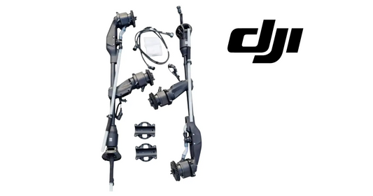
The DJI Agras T100 spraying system can be configured with the standard two-nozzle arrangement or DJI’s optional mist-nozzle configuration. Installing the DJI T100 Mist Spray Set is not a simple nozzle swap. The procedure requires removing the aircraft battery and payload platform, removing the original centrifugal spray lance, transferring and correctly orienting the solenoid valve, replacing the original spray-lance fixing base with the aluminum version, installing the M1 and M2 connection cables, adding the M3 motor signal cable and water pipe, and routing every hose and connector so the system can be reassembled without pinching, rubbing, leakage, or electrical strain.
This Ares Acres tutorial expands DJI’s installation video into a complete technician-facing guide. It preserves the demonstrated installation sequence while adding component identification, preparation, routing checks, common mistakes, troubleshooting, post-installation inspection, and clean-water testing guidance. It deliberately does not invent screw sizes, torque values, sealants, or calibration steps that are not supplied in DJI’s current kit instructions.
Ares Acres supports DJI Agras operators with aircraft, OEM replacement parts, diagnostics, technical education, and field-operation resources. For T100 equipment and support, explore the DJI Agras T100, DJI T100 Parts, DJI Agras Parts, DJI Accessories, the Ares Acres Product Catalog, or contact Ares Acres.
Prefer to watch instead of read? The video above demonstrates DJI’s physical installation sequence. Use this guide as a structured companion for identifying each connection, keeping removed hardware organized, checking flow direction, and verifying the installation before the aircraft returns to service.
What You’ll Learn
- How to place the T100 in a safe powered-off installation state.
- Why the flight battery must be removed before the payload is opened.
- How to release the four clamps on the central-frame arms.
- How to disconnect the payload bus cable safely.
- How to remove the aircraft or payload platform.
- How to open the upper and lower spray-lance fixing-base covers.
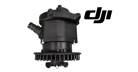
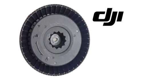
- How to remove the original centrifugal spray lance.
- How to disconnect its water pipe and motor connector.
- How to remove and transfer the solenoid valve.
- Why the arrow on the solenoid valve must point toward the outlet.
- How to reconnect the solenoid-valve signal wires.
- How to reinstall the inlet and outlet water pipes.
- Why the original spray-lance fixing base is replaced with an aluminum base.
- How to install the M1 and M2 spray-lance connection cables.
- How to route M1 and M2 through the water-tank slots and secure them with tape.
- How to install the mist spray lance in the original lance position.
- How to connect and secure the M3 centrifugal-motor signal cable.
- How to route M3 through the crossbar slot.
- How to remove the water-pipe T plug and install the M3 water pipe.
- How to reinstall the upper and lower cover plates.
- How to inspect the completed mechanical, electrical, and fluid connections.
- How to perform a conservative post-installation clean-water check.
Quick Answer: How Do You Install the DJI T100 Mist Spray Set?
Power Off Aircraft → Remove Flight Battery → Open Four Central-Frame Arm Clamps → Disconnect Payload Bus Cable → Remove Aircraft Platform → Pry Open Upper Fixing-Base Cover → Remove Two Upper Screws → Pry Open Lower Cover → Remove Two Lower Screws → Unscrew Lance Water Pipe → Disconnect Centrifugal-Motor Connector → Remove Original Centrifugal Spray Lance → Remove Solenoid Valve → Confirm Arrow Marks Outlet → Transfer Valve to New Mist Spray Lance → Reconnect Signal Wires and Water Pipes → Install Four Valve Screws → Replace Original Fixing Base With Aluminum Base → Remove Two Reserved-Interface Screws → Install M1 and M2 Cables → Route Them Through Tank Slots and Secure With Tape → Install Mist Spray Lance → Tighten Four Lance Screws → Connect and Clip M3 Motor Signal Cable → Route M3 Through Crossbar Slot → Remove Water-Pipe T Plug → Install M3 Water Pipe → Reinstall Upper and Lower Fixing-Base Covers → Inspect Before Restoring Power.
The three highest-risk mistakes are working with the battery installed, reversing the solenoid valve’s inlet and outlet orientation, and allowing a water pipe or M1/M2/M3 cable to become pinched when the platform and cover plates are reassembled.
What the Optional Mist Spray Configuration Changes
DJI lists the T100 standard sprinkler as the LX07550SX Standard Nozzle and the optional unit as the LX09550SX Mist Nozzle. DJI’s published specifications describe a two-nozzle standard arrangement and a four-nozzle optional arrangement.
| DJI T100 spraying-system specification | Standard configuration | Optional mist configuration |
|---|---|---|
| Sprinkler model | LX07550SX | LX09550SX |
| Listed sprinkler quantity | 2 | 4 |
| Listed maximum flow rate | 30 L/min | 40 L/min |
| Listed droplet-size range | 50–500 μm | 50–500 μm |
| Listed effective spray-width range | 5–13 m | 5–13 m, dependent on the actual operating scene |
These published values describe system capability, not a guaranteed result for every job. Effective width, deposition, drift, flow, and droplet behavior depend on aircraft settings, installed hardware, product, application rate, speed, altitude, wind, temperature, humidity, crop canopy, and calibration. Use the current official DJI Agras T100 specifications, kit documentation, and product label when configuring an actual operation.
Installation Overview: What Is Being Removed, Transferred & Added?
The mist-spray installation can be understood as five connected work phases.
| Phase | Main action | Critical verification |
|---|---|---|
| Power isolation and access | Remove the battery, release the four clamps, disconnect the payload bus, and remove the platform. | The aircraft cannot power unexpectedly and the payload is supported during removal. |
| Original lance removal | Open the fixing-base covers, remove four fixing screws, disconnect water and motor connections, and remove the lance. | No pipe, connector, wire, or housing is pulled by force. |
| Solenoid-valve transfer | Move the existing valve to the new mist spray lance. | The arrow-marked outlet faces the correct direction and the signal wires and pipes return to their proper connections. |
| Base and cable conversion | Replace the original fixing base, install M1/M2 at the reserved interface, and route them through the tank slots. | The aluminum base is seated correctly and both cables are secured without pinch points. |
| M3 completion and closure | Install the mist lance, connect M3, route it through the crossbar, replace the T plug with the M3 water pipe, and reinstall covers. | M3 is clipped and routed correctly, fluid fittings are secure, and covers close without pressure on hoses or wiring. |
Before You Begin: Safety, Cleanliness & Work-Area Preparation
This procedure opens the T100 spraying system and exposes fluid connections, electrical connectors, mounting hardware, and structural interfaces. Prepare the aircraft before touching the fixing base.
Aircraft State
- Land on a stable, level work surface.
- Stop all motors and spraying functions.
- Power the aircraft off completely.
- Remove the flight battery.
- Keep the battery physically away from the aircraft while work is underway.
- Do not reconnect power for convenience during disassembly.
Spray-System State
- Empty the tank and lines in accordance with the product label and operating procedures.
- Flush the system when required so technicians are not exposed to concentrated residue.
- Relieve any pressure using the current DJI and applicator procedure.
- Prevent rinse water or chemical residue from entering electrical connectors.
- Wear the personal protective equipment required for the most recently used product and for the cleaning process.
Work Area
- Use a clean, dry, well-lit surface.
- Support the payload platform so it cannot drop when the clamps are opened.
- Prepare labeled trays for upper-cover, lower-cover, solenoid-valve, interface, and lance hardware.
- Keep dirt away from open pipes, the solenoid valve, and removed plugs.
- Use protective caps or clean coverings when a fluid opening will remain exposed.
- Photograph original cable and hose routing before disconnecting anything.
Tools & Materials
The source tutorial explicitly uses a flathead screwdriver to open the spray-lance fixing-base cover plates. The complete job also requires the correct drivers for the installed screws and the components supplied with the DJI mist-spray kit.
Prepare:
- the compatible DJI T100 Mist Spray Set;
- the supplied mist spray lance or lances;
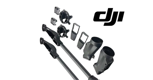
- the aluminum spray-lance fixing base;
- M1 and M2 spray-lance connection cables;
- the M3 centrifugal-motor signal cable;
- the M3 water pipe;
- the approved securing tape shown in the kit procedure;
- a flathead screwdriver used carefully for cover release;
- the correct screwdrivers or drivers for the installed fasteners;
- parts trays or labeled bags;
- clean caps or coverings for open fluid connections;
- clean water for post-installation testing when the current procedure permits; and
- the latest DJI installation documentation.
Do not substitute unknown screws, connectors, hose, tape, brackets, or valve components. Do not guess torque values. If DJI supplies a torque specification or thread-treatment instruction with the kit, use that value and method.
Identify the M1, M2 & M3 Connections Before Installation
The installation introduces three labeled connection paths. Keep their identities separate throughout the job.
| Connection | Role in the demonstrated procedure | Routing instruction |
|---|---|---|
| M1 | Spray-lance connection cable installed at the payload plate’s reserved interface. | Insert through the designated water-tank slot and secure with tape. |
| M2 | Second spray-lance connection cable installed beside M1. | Insert through its designated water-tank slot and secure with tape. |
| M3 signal cable | Centrifugal-motor signal connection for the added mist spray lance. | Connect to the motor, seat it in the bracket clip, and route it through the crossbar slot. |
| M3 water pipe | Fluid supply for the added spray position. | Remove the water-pipe T plug and install the M3 pipe in its place. |
Do not infer routing from cable length alone. Match the labels and the physical path shown in the current DJI procedure.
Step 1 — Confirm the Aircraft Is Powered Off
Verify that the T100 is fully powered off before beginning installation.
The aircraft should not be in standby, charging, updating, or connected to a power source. Confirm that displays, status indicators, pumps, and motors are inactive.
Step 2 — Remove the Aircraft Battery
Remove the flight battery from the aircraft.
This is the fundamental electrical-isolation step. Do not rely only on the power button. Physical battery removal prevents an accidental startup while the payload bus, motor connector, solenoid wires, and spray-system components are exposed.
Inspect the battery area for moisture or chemical residue before placing the battery aside. Store it where it cannot be knocked over, contaminated, or mistakenly reinstalled during the work.
Step 3 — Stabilize and Support the Payload Platform
Before opening the four clamps, make sure the aircraft and payload platform are supported.
Once the platform connections are released, its weight and attached components should not hang from the payload bus cable, water pipes, or a partially opened clamp. Use a second trained technician when necessary to control the platform safely.
Step 4 — Open the Four Central-Frame Arm Clamps
Open the four clamps located on the four arms of the central frame, one at a time.
Opening them sequentially helps the technician maintain control of the platform. As each clamp is released, check that the platform remains supported and no connection becomes tensioned.
Do not pry a clamp beyond its normal travel or force a latch that is still loaded by misalignment.
Step 5 — Disconnect the Payload Bus Cable
Disconnect the payload bus cable.
Grip the intended connector body or release mechanism. Do not pull on the wires. Before separating the connector, note its orientation and locking feature so it can be reinstalled correctly.
Inspect the connector for:
- moisture;
- chemical residue;
- damaged pins;
- bent contacts;
- a broken latch;
- corrosion; or
- a compromised seal.
If damage is present, stop and correct it before the aircraft returns to service.
Step 6 — Remove the Aircraft Platform
Remove the aircraft or payload platform as shown in the DJI procedure.
Lift it evenly and place it on a clean, supported surface. Make sure the disconnected bus cable and any nearby fluid paths move freely and do not catch on the frame.
Do not rest the platform on a spray lance, nozzle, connector, valve, or water fitting.
Step 7 — Pry Open the Upper Fixing-Base Cover Plate
Use a flathead screwdriver to carefully release the upper cover plate of the spray-lance fixing base.
The screwdriver is used as a controlled prying tool, not as a lever against nearby wiring or tubing. Place the tip only at the intended release location and apply the minimum force necessary.
Avoid:
- gouging the cover;
- damaging a seal or clip;
- slipping into a wire or hose;
- bending the plate; or
- prying against an unsupported plastic edge.
Step 8 — Remove the Two Upper Fixing-Base Screws
Remove the two screws on the upper portion of the spray-lance fixing base.
Place them in a labeled tray. Keep upper and lower hardware separated even if the screws appear similar; reinstall each fastener in the location specified by DJI.
Step 9 — Pry Open the Lower Fixing-Base Cover Plate
Use the flathead screwdriver to carefully release the lower cover plate.
Use the same controlled technique as the upper cover. Watch for cable or pipe routing behind the cover before pulling it away.
Step 10 — Remove the Two Lower Fixing-Base Screws
Remove the two screws from the lower part of the spray-lance fixing base.
At this point, four fixing-base screws have been removed: two upper and two lower. Continue supporting the spray lance so its weight does not transfer to the remaining water and electrical connections.
Step 11 — Unscrew the Water Pipe at the Spray-Lance Base
Unscrew the water pipe located at the base of the spray lance.
Keep the fitting aligned while loosening it. Avoid twisting the hose itself or loading the connected fitting sideways.
Once disconnected:
- protect the open line from dirt;
- contain any remaining clean water or residue;
- inspect the seal and mating surface;
- do not place the open end on the floor; and
- do not allow fluid to reach the motor connector.
Step 12 — Disconnect the Centrifugal-Motor Connector
Disconnect the centrifugal-motor electrical connector.
Release the locking feature before separating it. Pull from the connector housing rather than the cable. Note its orientation for later comparison with the M3 connection.
Step 13 — Remove the Entire Original Centrifugal Spray Lance
With the four fixing screws, water pipe, and motor connector released, remove the complete centrifugal spray lance.
Guide it out of the fixing base without scraping the connector, bending the pipe, or striking the aircraft frame. Set it on a padded, clean surface.
The solenoid valve will be transferred from this original assembly to the new mist spray lance, so keep the assembly organized and uncontaminated.
Step 14 — Remove the Four Solenoid-Valve Mounting Screws
Remove the four screws securing the solenoid valve.
Support the valve while the final screw is removed. Keep these fasteners separate from the spray-lance fixing-base screws.
Step 15 — Disconnect the Solenoid-Valve Inlet and Outlet Pipes
Disconnect both the inlet and outlet water pipes from the solenoid valve.
Before removal, photograph or label their positions. The valve is directional, and correct pipe placement must be restored on the new lance.
Inspect the pipe ends and valve ports for debris, damage, residue, or distorted sealing surfaces.
Step 16 — Remove the Two Solenoid Signal-Wire Screws
Remove the two screws securing the solenoid-valve signal wires.
Control the tool carefully so it does not slip across the wire terminals. Preserve any terminal orientation or hardware order shown by the original installation.
Step 17 — Remove the Solenoid-Valve Signal Wires
Lift the signal wires from their terminals after the retaining screws are removed.
Handle the terminals rather than pulling on the wire insulation. Keep the wire ends clean, dry, and separated from open water fittings.
Step 18 — Remove the Solenoid Valve
Remove the solenoid valve from the original spray lance.
This component will be reused on the new mist spray lance. Inspect it before transfer. Stop if the valve housing, arrow marking, ports, terminals, mounting points, or seals appear damaged.
Step 19 — Identify the Arrow-Marked Outlet
Locate the arrow molded, printed, or marked on the solenoid valve.
The arrow end is the outlet end.
This is the most important orientation reference in the valve-transfer procedure. Do not reinstall the valve based only on how the wires happen to reach. The inlet and outlet must follow the intended direction of fluid flow.
Solenoid Flow Check
| Check | Correct condition |
|---|---|
| Arrow is visible and understood | Technician can identify the outlet before mounting. |
| Valve position matches the new lance | Ports align without twisting or stretching pipes. |
| Inlet pipe reaches the inlet | Pipe is not crossed with the outlet path. |
| Outlet pipe reaches the arrow end | Flow direction follows the valve marking. |
| Signal wires reach naturally | Wires are not used to determine or force fluid orientation. |
Step 20 — Position the Solenoid Valve on the New Mist Spray Lance
Install the removed solenoid valve onto the new mist spray lance in the orientation shown by DJI.
Confirm the arrow-marked outlet faces the correct downstream water path before tightening any hardware. The valve should sit naturally in the bracket without being forced against the pipes or wiring.
Step 21 — Reinstall the Signal Wires and Tighten Their Two Screws
Place the solenoid signal wires onto their correct terminals and install the two retaining screws.
Tighten them securely according to DJI’s current specification. Do not overtighten small electrical-terminal hardware, and do not leave a terminal loose enough to move.
Check that:
- each wire is on the correct terminal;
- no conductor is exposed beyond the intended connection;
- insulation is not trapped under a screw incorrectly;
- the terminal cannot rotate freely; and
- the wires route away from sharp edges.
Step 22 — Seat the Valve in the Mist-Lance Bracket
Position the solenoid valve fully inside the spray-lance bracket.
The bracket should support the valve without distorting it. Confirm the mounting holes align before installing the four valve screws.
Step 23 — Install the Inlet and Outlet Water Pipes
Connect the inlet and outlet pipes to the transferred solenoid valve.
Use the arrow marking to confirm the outlet. Tighten both pipe connections securely using the method specified for the kit.
Do not apply unapproved sealant, thread tape, lubricant, or adhesive. The correct sealing method depends on the supplied fitting design and DJI instructions.
After connection, check that the pipes:
- are not crossed;
- do not kink;
- do not twist the valve;
- do not rub a sharp edge;
- have enough slack for the installed position; and
- cannot be trapped by the fixing-base covers.
Step 24 — Install the Four Solenoid-Valve Screws
Install the four screws that secure the valve to the mist spray lance.
Start all four before fully seating the assembly when the design permits, so the valve can align without being pulled sideways. Tighten them evenly using DJI’s specified method.
Verify that the valve remains in the correct flow orientation after fastening.
Step 25 — Remove the Original Spray-Lance Fixing Base
Remove the original spray-lance fixing base from the aircraft.
The source procedure does not provide permission to improvise additional disassembly. Remove only the fasteners and components required by the current DJI kit instructions.
As the original base comes away, note:
- its orientation;
- the surfaces it contacts;
- existing cable and hose paths;
- any spacers, clips, or seals; and
- the placement of retained hardware.
Step 26 — Install the Aluminum Spray-Lance Fixing Base
Replace the original base with the aluminum spray-lance fixing base supplied for the mist-spray installation.
Seat the aluminum base fully in the correct orientation. Confirm that:
- mounting surfaces are clean;
- no cable or pipe lies beneath the base;
- holes align without forcing;
- the base sits flat;
- the upper and lower covers can later close correctly; and
- the new mist lance can occupy the original lance position.
Use only DJI-specified hardware and torque values.
Step 27 — Remove the Two Reserved-Interface Screws From the Payload Plate
Locate the payload plate’s reserved interface and remove its two screws.
Keep these screws together because they will secure the M1 and M2 connection cables at the interface.
Inspect the interface area for moisture, residue, dirt, or obstruction before adding the cables.
Step 28 — Install the M1 and M2 Spray-Lance Connection Cables
Install the M1 and M2 spray-lance connection cables at the reserved interface.
Match each cable label to the position shown by DJI. Seat the connections squarely and completely. Do not force a connector that does not align; recheck its orientation and identification.
Step 29 — Tighten the Two Reserved-Interface Screws
Reinstall and tighten the two screws that secure the M1 and M2 cable connection at the payload plate.
The connection should be held securely without pinching the cable insulation or loading the connector at an angle.
Step 30 — Route M1 and M2 Through the Water-Tank Slots
Insert the M1 and M2 connection cables into their designated water-tank slots.
Correct routing protects the cables when the platform, tank, fixing base, and covers return to their operating positions.
Check that each cable:
- follows the intended slot;
- remains identifiable as M1 or M2;
- has no sharp bend at the connector;
- does not cross a water fitting improperly;
- stays clear of clamp and cover contact areas; and
- has enough controlled slack for assembly without forming a loose loop.
Step 31 — Secure M1 and M2 With Tape
Secure the routed M1 and M2 cables with tape as shown in the DJI procedure.
Use the appropriate material and placement. The tape should retain the cables without covering a connector release, interfering with drainage, trapping a hose, or leaving adhesive where it can contaminate a fluid fitting.
Do not use tape as a substitute for a connector that will not latch or a clip that is missing.
Step 32 — Install the Mist Spray Lance in the Original Position
Place the new mist spray lance into the position previously occupied by the original centrifugal spray lance.
Guide the lance, valve, pipes, and wires into position together. Do not allow the weight of the lance to hang from the solenoid wires or water pipes.
Confirm the lance is seated in the aluminum fixing base and aligned with the intended spray direction.
Step 33 — Install and Tighten the Four Spray-Lance Screws
Install the four fixing screws—two upper and two lower—and tighten them according to DJI’s specified sequence and torque.
Begin each screw without cross-threading. The lance should seat evenly rather than being pulled into alignment by one fully tightened screw.
After fastening, verify:
- the lance does not move in the base;
- the base remains flush;
- no pipe or wire is trapped;
- the valve bracket remains secure; and
- the upper and lower cover areas are unobstructed.
Step 34 — Connect the M3 Centrifugal-Motor Signal Cable
Connect the M3 centrifugal-motor signal cable to the new mist spray lance.
Align the connector, seat it completely, and engage its locking feature. Do not pull the cable tight across the lance or bracket.
Step 35 — Install the M3 Signal Cable in the Bracket Clip
Place the M3 signal cable into the designated bracket clip.
The clip controls movement and protects the cable from vibration, rubbing, and contact with other components. Confirm the cable is retained without crushing or sharply bending its insulation.
Step 36 — Route the M3 Signal Cable Through the Crossbar Slot
Insert the M3 motor signal cable into the crossbar slot shown in the DJI procedure.
Trace the cable from connector to slot. It should not:
- rub against a sharp edge;
- pass beneath a cover fastener;
- cross a moving or folding interface;
- interfere with the water pipe;
- become tensioned when the lance is in position; or
- form a loose loop that can snag during operation or service.
Step 37 — Remove the Water-Pipe T Plug
Locate and remove the plug from the water-pipe T connection.
Keep the fluid system clean while the port is open. Prevent debris, tape fragments, metal shavings, or chemical residue from entering the T fitting.
Retain the original plug in a labeled clean bag if DJI’s procedure calls for it to be kept for future configuration changes.
Step 38 — Install the M3 Water Pipe
Install the M3 water pipe at the newly opened T connection.
Seat and tighten the fitting securely using the approved method. Route the pipe so it reaches the M3 lance without kinking, twisting, rubbing, or interfering with the M3 signal cable.
M3 Fluid-Path Check
- T plug has been fully removed.
- Open T port remained clean.
- M3 pipe uses the correct fitting and orientation.
- Connection is fully seated.
- Pipe does not kink at the T or lance.
- Pipe cannot be pinched by a cover or platform.
- Solenoid outlet direction remains correct.
Step 39 — Reinstall the Upper Fixing-Base Cover Plate
Install the upper cover plate of the spray-lance fixing base.
Before snapping or seating it into place, look underneath. The plate should not press against a wire terminal, motor cable, water pipe, or connector.
If the cover does not seat naturally, stop and correct the routing. Do not force the cover closed over a trapped component.
Step 40 — Reinstall the Lower Fixing-Base Cover Plate
Install the lower cover plate.
Perform the same pinch-point inspection. Both cover plates should sit securely, evenly, and without abnormal gaps.
The source excerpt ends after cover installation. Before restoring power, complete every remaining platform-reinstallation and commissioning step required by the current DJI kit documentation. Do not assume that cover installation alone means the aircraft is ready to fly.
Post-Installation Mechanical Inspection
Inspect the entire installation while the battery is still removed.
Fixing Base and Lance
- Aluminum fixing base is fully seated.
- Four lance-fixing screws are present and secured.
- Upper and lower cover plates are installed correctly.
- Mist spray lance does not shift in the bracket.
- No cover is bowed or held open by a trapped component.
Solenoid Valve
- Four valve-mounting screws are present.
- Arrow-marked end remains connected as the outlet.
- Both signal-wire screws are installed.
- Terminals are secure and insulated correctly.
- Inlet and outlet pipes are on the correct ports.
M1, M2 and M3
- M1 and M2 are installed at the reserved interface.
- The two interface screws are secure.
- M1 and M2 follow the correct tank slots.
- Tape retains them without damaging or hiding connectors.
- M3 connector is fully seated.
- M3 is retained in the bracket clip.
- M3 follows the crossbar slot.
- No cable is pinched, stretched, or rubbing.
Fluid System
- Original open connections are closed.
- M3 pipe replaces the T plug correctly.
- No fitting is visibly crooked.
- No pipe is kinked.
- No fluid residue is present at electrical connectors.
- All protective caps and temporary coverings have been removed where required.
Reinstalling the Platform and Restoring the Aircraft
The initial disassembly removed the aircraft platform, disconnected the payload bus, and opened all four central-frame clamps. Those connections must be returned to their correct operating state before power is restored.
Follow the current DJI kit procedure to:
- Position the platform correctly without trapping M1, M2, M3, or any water pipe.
- Reconnect the payload bus cable in its original orientation.
- Confirm the connector lock is fully engaged.
- Seat the platform evenly on the central frame.
- Close each of the four arm clamps completely.
- Inspect the platform from all sides for uneven seating or interference.
- Reconfirm cable and hose freedom after the clamps are closed.
- Install the aircraft battery only after the dry inspection is complete.
If the official procedure for the installed kit differs, follow the current official procedure.
First Power-On After Installation
Restore power only after the mechanical, electrical, and fluid inspections pass.
At first power-on:
- keep people clear of propellers, pumps, and spray components;
- keep the aircraft stationary on a stable surface;
- watch for payload, motor, valve, or communication errors;
- do not command spray output immediately;
- confirm the controller recognizes the installed system as expected; and
- power down if there is odor, heat, smoke, abnormal sound, connector error, or unexpected pump or motor behavior.
Do not troubleshoot a questionable electrical connection with the battery installed and covers open unless a current DJI diagnostic procedure explicitly requires live testing by a qualified technician.
Clean-Water Leak & Function Check
The first fluid test should use clean water when allowed by the current DJI commissioning instructions. Do not introduce pesticide, fertilizer solution, or another active product into an unverified installation.
Before Flow
- Tank and system are suitable for a clean-water check.
- All electrical connectors are dry.
- Every fitting is visible enough to inspect.
- Personnel are wearing appropriate eye and skin protection.
- Discharge is contained in an approved area.
During Flow
- Observe the transferred solenoid valve.
- Inspect the inlet and arrow-marked outlet connections.
- Inspect the M3 pipe at the T connection and lance.
- Watch for seepage, drips, swelling, or a moving fitting.
- Listen for abnormal pump, valve, or centrifugal-motor sounds.
- Confirm the expected spray positions respond through the current DJI test procedure.
After Flow
- Stop the system and power down.
- Remove the battery before touching or retightening components.
- Inspect again for delayed seepage.
- Correct any leak using the approved fitting and seal method.
- Repeat the check before loading an application product.
Never tighten an electrical-adjacent water connection while the aircraft is powered unless DJI explicitly requires and controls that procedure.
Installation Sequence Checkpoint Table
| Checkpoint | Must be true before continuing |
|---|---|
| Platform removal | Battery removed, platform supported, payload bus disconnected. |
| Original lance removal | Upper and lower screws removed, water pipe and motor connector released. |
| Valve transfer | Arrow outlet identified, pipes labeled, signal wires protected. |
| New valve installation | Two signal screws, pipes, and four mounting screws installed correctly. |
| Base replacement | Aluminum base seated with no trapped wiring or pipe. |
| M1/M2 installation | Both labels matched, interface secured, cables routed through slots and taped. |
| Mist lance installation | Four fixing screws installed and lance stable. |
| M3 signal path | Connector seated, cable clipped, crossbar slot used. |
| M3 fluid path | T plug removed cleanly and M3 pipe fully installed. |
| Cover closure | Upper and lower plates close without force or pinching. |
| Power restoration | Platform, bus cable, clamps, and all dry checks complete. |
Common DJI T100 Mist Spray Set Installation Mistakes
1. Leaving the Battery Installed
Powering the aircraft off is not a substitute for physically removing the flight battery before exposing the payload bus and motor connections.
2. Letting the Platform Hang From the Payload Bus Cable
Support the platform before opening the clamps and disconnect the cable without loading its wires or connector.
3. Mixing Upper, Lower, Valve and Interface Screws
Keep each hardware group labeled. Similar appearance does not prove interchangeability.
4. Damaging a Cover With the Flathead Screwdriver
Use the minimum force at the intended release point and keep the tool away from wires and pipes.
5. Pulling a Connector by Its Wires
Release the lock and handle the connector body.
6. Allowing Dirt Into an Open Water Pipe
Cap or protect open fluid paths immediately.
7. Reversing the Solenoid Valve
The arrow identifies the outlet. Confirm flow direction before installing the pipes and mounting screws.
8. Crossing the Inlet and Outlet Pipes
Label or photograph them before removal and verify the arrow-marked outlet during reassembly.
9. Using Signal-Wire Reach to Decide Valve Direction
Wire reach does not define fluid flow. Orient the valve by its arrow and intended water path.
10. Overtightening Small Terminal Screws
Secure the signal wires using DJI’s method without damaging terminals or threads.
11. Reusing the Original Fixing Base Instead of the Aluminum Base
The demonstrated mist-spray conversion replaces the original base with the supplied aluminum fixing base.
12. Swapping M1 and M2
Follow the printed labels and DJI positions rather than assuming the cables are interchangeable.
13. Routing M1 or M2 Outside the Water-Tank Slots
Incorrect routing can create pinch, abrasion, or reassembly problems.
14. Using Tape to Hide a Loose Connector
Tape secures routing; it does not repair a connector that has not latched.
15. Leaving M3 Outside the Bracket Clip
The clip controls cable movement and protects it from vibration and rubbing.
16. Skipping the Crossbar Slot
The M3 signal cable should follow the demonstrated crossbar path.
17. Forgetting to Remove the Water-Pipe T Plug
The M3 fluid line cannot be installed correctly until the intended T port is opened.
18. Forcing a Cover Over a Pipe or Cable
If a cover will not seat naturally, inspect routing instead of applying more pressure.
19. Filling With Chemical Before Leak Testing
Use a conservative clean-water commissioning process first when permitted.
20. Flying Without a Final Payload and Controller Check
Mechanical completion does not prove the controller recognizes and operates the new configuration correctly.
Troubleshooting the Mist Spray Set Installation
| Problem | Likely cause | What to inspect |
|---|---|---|
| Platform will not lift away cleanly | Clamp still closed, bus cable still connected, or platform unsupported | Recheck all four clamps and the payload bus connection with the battery removed. |
| Fixing-base cover will not release | Tool is at the wrong pry point or a fastener remains | Confirm the DJI release location and avoid excessive force. |
| Original lance will not come out | Water pipe, motor connector, or one of four fixing screws remains attached | Recheck two upper screws, two lower screws, fluid fitting, and motor connector. |
| Solenoid pipes do not reach naturally | Valve is reversed or pipes are crossed | Reorient using the arrow-marked outlet and original routing reference. |
| Valve bracket holes do not align | Valve is not seated or wrong orientation was used | Stop tightening, reseat the valve, and verify the kit diagram. |
| Signal wire terminal moves | Retaining screw is not seated or terminal order is wrong | Power remains isolated; reinstall using DJI’s terminal arrangement. |
| Aluminum base does not sit flat | Cable, pipe, debris, or retained hardware is underneath | Remove the base and correct the obstruction. |
| M1/M2 interface connector will not seat | Wrong orientation, label, or connector alignment | Verify M1/M2 positions and inspect pins before applying force. |
| M1/M2 cables interfere with platform closure | They are outside designated tank slots or have excess loose cable | Reroute through the slots and secure as demonstrated. |
| Mist lance moves after four screws are installed | Base is not seated, screws are misplaced, or tightening is uneven | Remove power, inspect hardware and base alignment, and use DJI’s procedure. |
| M3 cable is too tight | Cable missed the bracket clip or crossbar path | Reroute through both specified retention points. |
| M3 water pipe kinks | Pipe path or fitting orientation is incorrect | Reposition without twisting and verify both endpoints. |
| Upper or lower cover will not close | Pipe, cable, connector, or valve position obstructs it | Open the cover and correct routing; do not force it. |
| Leak appears at solenoid inlet or outlet | Fitting is loose, misaligned, contaminated, or sealed incorrectly | Power off, remove battery, inspect the correct DJI sealing components and flow orientation. |
| Leak appears at the T connection | M3 pipe is not fully seated or fitting/seal is damaged | Isolate power and repair with the approved component. |
| Controller reports a spray-motor or payload error | M1/M2/M3, payload bus, or motor connector is incomplete or damaged | Power down and inspect every connector, label, latch, pin, and cable route. |
| One spray position does not operate | Electrical or fluid connection to that lance may be incomplete | Inspect the associated cable, solenoid, motor connector, and water pipe. |
| Spray behavior is uneven after installation | Configuration, calibration, blockage, pressure, flow, or route settings may be incorrect | Verify hardware first, then perform DJI’s current setup and calibration procedures. |
Ares Acres Recommended Installation Workflow
- Confirm kit compatibility with the exact T100 configuration and region.
- Review the complete DJI installation video and current kit documentation before disassembly.
- Empty, clean, and make the spray system safe for service.
- Power the aircraft off and remove the battery.
- Photograph the original payload, cable, valve, and pipe routing.
- Support the platform and open the four clamps one by one.
- Disconnect the payload bus by its connector body.
- Remove and support the aircraft platform.
- Open the upper and lower fixing-base covers carefully.
- Organize the two upper and two lower screws separately.
- Disconnect the original lance’s water pipe and motor connector.
- Remove the original centrifugal spray lance.
- Label inlet, outlet, and signal connections before valve removal.
- Remove the four valve screws, two water pipes, and two signal-wire screws.
- Identify the arrow-marked outlet before transferring the valve.
- Install the valve on the new mist lance in the correct direction.
- Secure the signal wires, bracket, water pipes, and four valve screws.
- Replace the original fixing base with the aluminum base.
- Install M1 and M2 at the reserved payload-plate interface.
- Route both through the designated tank slots and secure them with tape.
- Install the mist spray lance and its four fixing screws.
- Connect M3 and seat it in the bracket clip.
- Route M3 through the crossbar slot.
- Remove the T plug and install the M3 water pipe.
- Recheck valve direction, every fitting, and every connector.
- Close the upper and lower cover plates without force.
- Reinstall the platform, payload bus, and four clamps according to DJI’s current instructions.
- Complete a battery-removed mechanical and pinch-point inspection.
- Restore power and check controller recognition and error messages.
- Perform a controlled clean-water leak and function check when permitted.
- Power down and reinspect before loading an application product.
- Complete any DJI-required setup, calibration, or firmware step.
- Perform the DJI Agras T100/T50 Pre-Flight Safety Tutorial before flight.
Related DJI Agras Operator Academy Tutorials
- DJI Agras T100/T50 Pre-Flight Safety Tutorial
- DJI Agras T100 Route Mode Field Planning & Task Execution
- DJI Agras T100/T50 Remote Operation View Tutorial
- DJI Agras Remote Controller Activation Tutorial
- DJI Agras T100 D-RTK 3 Tutorial
- DJI Agras T100 A-B Operation Mode Tutorial
- DJI Agras T100 Manual & Manual Plus Tutorial
- The DJI T100 Spreading System Tutorial
FAQ: DJI Agras T100 Mist Spray Set Installation
Does the aircraft need to be powered off?
Yes. The aircraft must be fully powered off before installation.
Should I remove the battery?
Yes. DJI’s demonstrated procedure begins with battery removal. Do not expose payload and motor connections with the flight battery installed.
How many central-frame clamps are opened?
Four clamps—one on each of the four central-frame arms—are opened one by one.
What cable is disconnected before the platform is removed?
Disconnect the payload bus cable after supporting the platform and opening the clamps.
How are the fixing-base covers opened?
The tutorial uses a flathead screwdriver to pry open the upper and lower cover plates carefully.
How many original lance-fixing screws are removed?
Four total: two from the upper part of the fixing base and two from the lower part.
What must be disconnected before removing the original centrifugal lance?
Unscrew the water pipe at the lance base and disconnect the centrifugal-motor connector after the fixing screws are removed.
Is the solenoid valve replaced?
The demonstrated procedure transfers the solenoid valve removed from the original lance onto the new mist spray lance.
How many screws secure the solenoid valve?
Four mounting screws secure the valve to the lance bracket. Two additional screws secure its signal wires.
Which end of the solenoid valve is the outlet?
The arrow-marked end is the outlet end.
Why does solenoid-valve direction matter?
The valve controls a directional fluid path. Reversing inlet and outlet can prevent correct operation or produce abnormal flow behavior.
Should I use sealant or thread tape on the water fittings?
Use only the sealing method specified by DJI for the supplied fittings. Do not add an unapproved material.
Why is the spray-lance fixing base replaced?
The mist-spray installation procedure replaces the original base with the supplied aluminum spray-lance fixing base to support the new configuration.
Where are M1 and M2 installed?
They are installed at the payload plate’s reserved interface and secured with the two interface screws.
How are M1 and M2 routed?
Insert them into the designated water-tank slots and secure them with tape as shown by DJI.
Where is the mist spray lance installed?
It is installed in the original spray-lance position and secured with four screws.
What is the M3 signal-cable path?
Connect M3 to the centrifugal motor, retain it in the bracket clip, and route it through the crossbar slot.
What happens to the water-pipe T plug?
Remove the T plug and install the M3 water pipe at that connection.
Can I force the cover plates closed?
No. If a cover will not sit naturally, inspect for a trapped pipe, cable, connector, or misaligned component.
When should the battery be reinstalled?
Only after the complete battery-removed inspection, correct platform reinstallation, payload-bus reconnection, and clamp closure.
What should I use for the first leak check?
Use clean water when permitted by DJI’s current commissioning procedure. Avoid loading an active product into an installation that has not passed a leak and function check.
What should I do if a leak appears?
Stop the test, power the aircraft down, remove the battery, and repair the fitting using the approved DJI component and sealing method before testing again.
Do I need to calibrate the system after installation?
Complete every setup, calibration, recognition, or firmware step required by the current DJI Agriculture app and mist-spray kit documentation. The supplied transcript does not specify a calibration sequence, so do not invent one.
What are DJI’s listed T100 mist-nozzle specifications?
DJI lists the optional LX09550SX Mist Nozzle, four optional sprinklers, a maximum system flow rate of 40 L/min in the four-nozzle configuration, a 50–500 μm droplet-size range, and an effective width of 5–13 m depending on the operating scene.
Does installing the kit guarantee a specific spray width or droplet result?
No. Actual performance depends on the complete configuration, material, calibration, altitude, speed, wind, environment, crop, and operating settings.
Can an untrained operator perform this installation?
The job opens electrical, fluid, and structural payload connections. If the installer cannot identify the components, preserve flow direction, route the cables correctly, or follow DJI’s service instructions, use a qualified DJI Agras technician.
Final Takeaway
The DJI Agras T100 Mist Spray Set installation is a coordinated mechanical, electrical, and fluid-system conversion. It begins with complete power isolation and platform removal, continues through careful disassembly of the original centrifugal lance, and depends on transferring the solenoid valve in the correct flow direction.
The arrow-marked end of the valve must remain the outlet. M1 and M2 must be installed at the reserved payload-plate interface, routed through the water-tank slots, and secured. M3 must connect to the centrifugal motor, sit in the bracket clip, pass through the crossbar slot, and receive water through the T connection after its plug is removed. The aluminum fixing base and both cover plates must seat without trapping any pipe or cable.
The installation is complete only after the platform and payload bus are restored correctly, the four clamps are locked, a battery-removed inspection passes, the controller recognizes the system, and a conservative clean-water check confirms that the valve, pipes, connectors, and spray positions operate without leakage or error.
Complementary DJI T100 Equipment & Technician Resources
Mist-spray performance depends on the entire T100 spraying platform, not only the new lance. Inspect the aircraft, power system, fluid delivery components, controller, and replacement parts before returning the system to field service.
- DJI Agras T100 Aircraft — explore the T100 platform and complete-system options.
- DJI T100 Parts — browse model-specific OEM replacement components.
- DJI Agras OEM Parts — search the broader agricultural-drone parts catalog.
- DJI Agras Accessories — review operational accessories and supporting equipment.
- Ares Acres Product Catalog — search aircraft, spraying components, power equipment, and field-support products.
- Ares Acres Technical Support — contact our team for component identification, installation support, or T100 equipment questions.
What Is Ares Acres?
Ares Acres is a U.S.-based agricultural robotics company focused on DJI Agras aircraft, OEM parts, operator support, diagnostics, and technical education. Our growing DJI Agriculture Tutorials library is designed to help owners and operators understand the systems they use in the field—not simply purchase them.
Need DJI Agras T100 Parts or Support?
Explore the DJI Agras T100, browse DJI T100 Parts, search the complete DJI Agras Parts catalog, or contact Ares Acres for help identifying the right component or system for your operation.
Installation and operational note: Component design, cable labels, fasteners, torque values, sealing methods, installation sequence, recognition, calibration, and available functions can vary by kit revision, aircraft configuration, firmware, DJI Agriculture app version, and region. Verify compatibility and follow the latest official DJI installation and service documentation. Keep the aircraft powered off with the flight battery removed during mechanical, electrical, and fluid-system work unless an official diagnostic procedure explicitly requires otherwise. Handle pesticide residue and rinse water according to the product label and applicable laws. Do not return the aircraft to service until all covers, clamps, connectors, pipes, payload components, safety checks, and required calibrations have been completed and verified.