
DJI Agras T100 Tutorial: How Plan Fields and Execute Tasks
Share
🇺🇸 U.S.A. FIRST — DJI Agras T100 Route Mode, Field Planning & Operator Support
Ares Acres is a U.S.-based agricultural robotics company focused on DJI Agras aircraft, OEM parts, positioning systems, power systems, maintenance components and practical operator education. Our goal is to help commercial agricultural drone operators understand the equipment, plan missions correctly and move from a field question to the correct aircraft, component or technical resource without searching through an unrelated consumer-drone catalog.
This tutorial is part of the Ares Acres DJI Agras Operator Academy. It explains how to plan fields and execute reusable tasks in Route Mode on the DJI Agras T100, with special attention to RTK-assisted controller planning, aircraft-based point capture, obstacles, non-application areas, connection routes, preflight checks and task-resume workflows.
Explore Ares Acres: Ares Acres Home · Full Product Catalog · DJI Agras Parts · DJI Agras T100 Parts · DJI Accessories · DJI Agras T100 · Contact Ares Acres
Watch: DJI Agras T100 Field Planning and Route Mode Task Execution
Quick Answer: What Is Route Mode on the DJI Agras T100?
Route Mode is a planned-operation workflow in which the operator first defines the field boundary, obstacles and any areas where application should be disabled. The resulting field can be saved and reused for future operations. Once a field is loaded, the operator configures the application parameters, verifies the connection route and return-to-home settings, and then starts the automated task.
The workflow is particularly useful for larger fields where repeated manual flying would create unnecessary workload. The tutorial describes Route Mode as well suited to large fields with a moderate number of obstacles and relatively minor rolling terrain. It is not a substitute for pilot judgment: the operator remains responsible for the field plan, obstacle information, legal operating requirements and safe execution of the mission.
What You Will Learn
- How Route Mode differs from manual operation and why saved fields matter.
- The three field-planning methods: map crosshair, controller point capture and aircraft point capture.
- How RTK-assisted controller planning works and why it is preferred over lower-precision controller satellite positioning when available.
- How to configure Custom Network RTK before measuring a field.
- How to add, move and delete boundary points without creating crossing boundaries.
- How to map irregular obstacles, round obstacles and non-application areas.
- How to plan a regular field efficiently by flying the aircraft over boundary points.
- How to configure application rate, flight speed, height and other task settings after planning.
- How connection points and return points help manage the path between takeoff and the working route.
- What to verify in the preflight auto-check before starting.
- How to pause for refill or battery replacement and then resume an unfinished task.
- How to review the task summary and reopen an unfinished saved field later.
Recommended T100 and RTK Resources
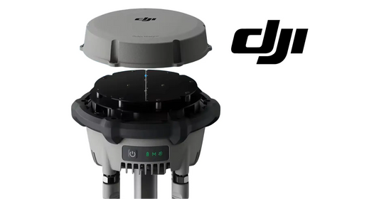
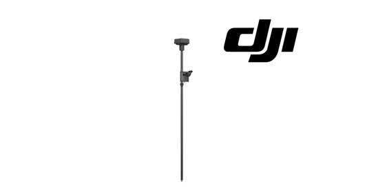
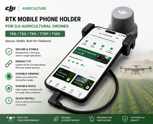
For operators building a precision-positioning workflow around the T100, Ares Acres maintains the DJI Agras T100 D-RTK 3 High-Precision GNSS Mobile Station, the DJI Agras T100 OEM Remote Controller, the DJI Agras Universal RTK Mobile Phone Stand, the DJI Agras T100 OEM RTK Antenna Module and the DJI Agras T100 OEM RTK Mushroom Head Adapter & Connector.
If your first question is how to configure the mobile station itself, read the Ares Acres DJI Agras T100 D-RTK 3 setup tutorial before continuing with field planning.
The Three DJI Agras Field-Planning Methods
| Method | Reference | Best Use | Key Consideration |
|---|---|---|---|
| Crosshair on Map | Map location | Planning from an accurate HD map | The video recommends pairing this method with an HD map generated through mapping. |
| Add Point With Controller — RTK | Remote-controller position | Walking the boundary with higher planning precision | Requires the appropriate RTK positioning hardware and a valid RTK solution. |
| Add Point With Controller — Satellite | Remote-controller GNSS position | Planning when RTK hardware is unavailable | The tutorial identifies this as relatively lower precision than RTK positioning. |
| Add Point With Aircraft | Aircraft position | Regular fields, few obstacles, experienced manual operators | Requires safe manual flight around the field and clear obstacle awareness. |
Before You Plan a Field
Field planning should begin with the same discipline as a flight. Confirm the property and intended treatment area, inspect obstacles that may not be obvious from imagery, understand where people, roads, power infrastructure, trees, structures and sensitive areas are located, and determine whether a saved field already exists. If the plan will be reused, accuracy at this stage becomes even more important because the geometry can influence many future operations.
For a complete RTK setup workflow, use the D-RTK 3 calibration guide together with the newer D-RTK 3 linking, PPP and Network RTK guide.
Method 1: Planning With the Map Crosshair
The crosshair method lets the operator place planning points directly on the map rather than physically carrying the controller around the boundary or flying the aircraft over each point. The tutorial specifically recommends using this method together with a high-definition map generated from a prior mapping process. The quality and alignment of the map matters: an imprecise background image can produce an imprecise field boundary even if the points look visually correct on the screen.
This method is attractive when a reliable recent map exists and the field is easy to interpret from above. For complex edges, new obstacles or uncertain boundaries, physical verification remains important.
Method 2: Add Point With Controller Using RTK
1. Install the RTK Positioning Hardware
In the video workflow, the RTK positioning accessory is mounted to the remote controller using the extension bracket and its fixing hardware. Once attached, the controller can use the RTK solution as the reference for boundary-point measurement instead of relying only on its built-in satellite positioning.
If the RTK accessory is not detected, the controller can fall back to satellite positioning. That can still be useful, but the tutorial recommends RTK for higher planning precision where the required hardware and service are available.
2. Connect the Controller to Custom Network RTK
For the Custom Network RTK example shown in the tutorial, the remote controller needs an internet connection so it can reach the RTK correction service. The aircraft itself does not need to be powered on merely to walk the field boundary with the controller.
- Open the Agras operating interface and tap Begin.
- Open the operation-mode switch in the upper-left area and select Route.
- Open the settings menu and enter the RTK settings.
- Select Custom Network RTK as the RTK signal source.
- Enter the credentials/login information required by the network RTK provider.
- Confirm the connection and return to the Route Mode planning screen.
- Select Field as the task type.
- Tap Add and choose Add Point With Controller.
The number of RTK satellites/positioning status is displayed when RTK positioning is active. Do not begin measuring simply because the screen is open. Wait until the positioning state is ready and the interface indicates a usable solution, as shown by the green status in the tutorial.
3. Walk the Field Boundary
Carry the remote controller along the physical boundary. At each meaningful change in direction, stop at the desired reference point and tap Add. The goal is not to create the maximum possible number of points; it is to create enough correctly placed points to describe the real boundary cleanly.
Boundary points must be added in sequence and the boundary must not cross itself. Crossing point order can prevent the software from generating a usable flight route. If a point is misplaced, select it and drag it to the correct location. The tutorial also shows that a point can be deleted and added again when necessary.
How to Map Obstacles Correctly
Irregular or Large Obstacles
Change the point type to the obstacle-planning option and trace the obstacle boundary rather than treating it as part of the field edge. This can be used for structures, tree clusters or other areas the aircraft should route around.
Round Obstacles Such as Power Poles
For approximately circular obstacles, select the round-obstacle point type, position the circle over the obstacle and add it. The training video appears to show a default radius of approximately 1.5 m; the supplied transcript renders this as “1.5 mm,” which is clearly inconsistent with field-scale obstacle planning. Treat the displayed value in your current Agras software as authoritative.
The radius can be changed by dragging the obstacle boundary. The center can be moved to correct the obstacle position, and the obstacle can be removed when necessary. A round obstacle should be large enough to represent the real hazard and the safety margin appropriate to the operation, not merely large enough to cover the icon on the map.
How to Create Non-Application Areas
The transcript’s “non-lication” wording refers to non-application areas: zones inside the overall field where the aircraft may need to transit but should not spray or spread material. These can be useful when the field contains an internal area that must remain untreated.
Do not confuse a non-application area with an obstacle. A non-application zone controls material application; an obstacle represents something the aircraft needs to avoid. Which geometry is appropriate depends on the actual site and mission.
Save the Field for Future Operations
Once the field boundary, obstacles and internal non-application zones are correct, tap Save, assign the field a clear name and save it again. Use a naming system that can be understood months later by another operator. A farm or customer name plus field identifier is usually more useful than a generic name such as “Field 1.”
The permanent field record is one of Route Mode’s biggest operational advantages. A carefully planned field can reduce repeated setup work on subsequent visits while preserving the obstacle and boundary information the team has already collected.
Method 3: Add Point With Aircraft
Aircraft-based planning can be faster when the field is regular, the obstacle count is low and the operator is experienced with manual flight. Instead of walking the edge, the aircraft itself becomes the positioning reference.
- Tap Begin.
- Select Route from the operation-mode switch.
- Select Field as the task type.
- Tap Add and choose Add Point With Aircraft.
- Wait until the aircraft status is ready for normal flight.
- Manually fly the Agras aircraft along the field boundary.
- The tutorial recommends approximately 3–5 m of flight height during this planning example while monitoring the FPV view and obstacles ahead.
- Use the camera-control dial when needed to improve the FPV viewing angle.
- When the aircraft is directly above the intended boundary point, tap Add.
- For large obstacles, fly around the obstacle and record its boundary points when safe and appropriate.
- After planning is complete, land the aircraft before moving into task configuration.
The 3–5 m figure is an instructional example from the video, not a universal safe altitude for every field. Terrain, crop height, wires, trees, structures, people, aircraft configuration, visibility and applicable operating rules all matter.
Controller Planning vs Aircraft Planning: Which Should You Use?
Controller + RTK is often preferable when precise physical boundary measurement is required and walking the site is practical. It lets the operator inspect the boundary and obstacles at ground level while recording points. Aircraft planning can be much faster for a clean, regular field, but it places more emphasis on the operator’s manual-flight skill and ability to identify obstacles from the air.
If you are working across multiple saved plots, also read the DJI T100 multiple-field and autonomous-flight tutorial.
Load the Saved Field and Configure the Task
After field planning is complete, select Use to turn the saved geometry into an executable operation. At this stage, the boundary is only one part of the mission. The operator still has to configure the application and flight parameters for the actual job.
Application Rate
Enter the required application rate based on the intended operation and applicable product instructions.
Droplet Size
The training video gives examples in which smaller droplets may be selected for certain tall-crop, low-wind conditions and larger droplets may be used for some herbicide operations to reduce drift. These examples should not be treated as blanket chemical-application recommendations. The pesticide/product label, nozzle or atomizer configuration, legal requirements, weather, crop, target, buffer restrictions and operator’s approved application plan take precedence.
Flight Speed and Height
Set flight speed and height relative to the crop according to the actual field, crop canopy, application target, aircraft configuration, wind and legal/safety requirements. A setting that works in one crop or field should not automatically be copied to another.
For spreading rather than spraying, see the DJI T100 Spreading System programming and calibration tutorial.
Connection Points: Managing the Path From Takeoff to the Route
The automated working route may begin some distance from the takeoff point. If obstacles exist between takeoff and the route start, the operator can add multiple connection points to shape the transit path.
- Drag a connection point to change its location.
- Delete a connection point if it no longer belongs in the route.
- Do not assume a connection route will remain valid in every circumstance.
- The tutorial warns that connection points can become invalid if obstacle-avoidance behavior is triggered during flight.
- If there are persistent obstacles between the takeoff area and the field, add them to the saved field/operation plan rather than relying only on an improvised transit path every time.
The goal is to make the connection route explicit and repeatable, while still recognizing that obstacle sensing and pilot intervention can alter the real flight path.
Using Return Points to Bypass Obstacles
Route Mode also supports return-point logic for navigating around obstacles encountered in the operating environment. Treat return routing with the same care as the working route: verify the altitude, path and obstacle environment rather than assuming “Return” automatically means “safe.”
Preflight Auto-Check Before Starting the Task
Tap Start to open the preflight auto-check window. Before authorizing takeoff, review the mission rather than immediately sliding to start.
| Check | Why It Matters |
|---|---|
| Field boundary and route | Confirms the aircraft is operating in the intended area and the route was generated correctly. |
| Obstacles and non-application zones | Confirms hazards and treatment exclusions are represented correctly. |
| Connection routing | Determines how the aircraft moves between takeoff and the working route. |
| Connection/RTH speed | Must be appropriate for the site and obstacle environment. |
| Connection/RTH altitude | Must provide appropriate clearance for known terrain and obstacles while complying with operating limits. |
| Application parameters | Rate, flight speed, height and application settings must match the current job. |
| Positioning and aircraft status | Do not launch a precision route with unresolved positioning or aircraft-status warnings. |
When all settings are correct, the tutorial shows that the operator can authorize the task through the on-screen start action or the applicable remote-controller control. The aircraft can then take off automatically and enter the route.
When Manual Flight to the Route Start Is Safer
Automatic takeoff is not always the best first move. If the area around the takeoff point is constrained or complex, the tutorial recommends manually controlling the Agras aircraft to the route start before beginning the automated task. This gives the pilot direct control through the highest-complexity portion of the departure instead of asking the automated connection route to solve a poor launch location.
Route Mode is automation, not permission to ignore takeoff-site selection. A better launch point can be more valuable than a more complicated connection route.
What Happens When the Tank Is Empty or the Battery Is Low?
During a Route Mode operation, the remote controller can alert the operator when application material is depleted or the aircraft battery reaches the relevant low-battery condition. The workflow shown in the video is:
- Respond to the controller warning.
- Return the aircraft to the servicing/takeoff location under the appropriate control mode.
- Refill the application tank or replace/service the battery as required.
- Confirm the aircraft and application system are ready to continue.
- Select Resume so the saved task continues from the remaining work rather than restarting the entire field.
For T100 power-system operation, battery charging and generator workflow, see the DJI T100 Power Supply Tutorial.
Ending a Task and Reviewing the Summary
When the route is complete, tap End and review the task summary. The tutorial highlights core records such as worked area, elapsed time and spraying/application amount. Operators should treat the summary as an operational record rather than a screen to dismiss immediately.
If the job is not complete, the unfinished task can remain in the field/task list and be reopened later. That makes Route Mode valuable for multi-battery jobs, interrupted operations, weather delays and fields that cannot be completed in one continuous sortie.
Ares Acres Route Mode SOP
- Inspect: verify field identity, boundaries, obstacles, sensitive areas, takeoff point and operational constraints.
- Choose the planning method: HD-map crosshair, controller + RTK, controller satellite positioning or aircraft point capture.
- Establish positioning: verify the RTK/network or GNSS state before recording points.
- Build the boundary sequentially: add corner points in order and eliminate crossing geometry.
- Add obstacle geometry: map irregular and round obstacles with realistic margins.
- Add non-application zones: identify internal areas where spraying/spreading must be disabled.
- Save and name the field: use a repeatable naming convention.
- Load the field: choose Use and configure the actual application task.
- Set application parameters: follow the product label, approved operating plan and current conditions.
- Build the connection route: add connection points where necessary and verify the path from takeoff to the route.
- Review RTH/connection settings: verify speed, altitude and obstacle environment.
- Execute: authorize automated operation only after all preflight checks pass.
- Service and resume: refill/change battery when prompted, then resume the remaining task.
- Close and record: end the mission, review the summary and retain the field for future use.
Common Route Mode Planning Mistakes
- Starting before positioning is ready. Recording boundary points before an RTK/GNSS solution is stable can degrade the plan.
- Crossing boundary-point order. Points must describe the perimeter sequentially; crossing geometry may prevent route generation.
- Using too few points on an irregular boundary. A saved straight segment may cut across an area that is not actually part of the field.
- Using too many noisy points. Unnecessary points can make the boundary harder to review and edit.
- Treating non-application zones as obstacles. These features solve different operational problems.
- Ignoring the transit path from takeoff to field. A perfect field route can still have an unsafe connection route.
- Assuming connection points cannot change. Obstacle-avoidance actions may invalidate or alter connection behavior.
- Copying another job’s spray settings. Application rate, droplet size, speed and height must be verified for the current product and conditions.
- Automatically taking off from a constrained location. Manual positioning at the route start may be more appropriate in complex surroundings.
- Failing to save the field clearly. Poor naming reduces the long-term value of reusable field plans.
- Skipping the task summary. Completed area, time and applied volume are valuable for operational records and troubleshooting.
Troubleshooting Route Mode
| Problem | Check First |
|---|---|
| Cannot generate a route | Look for crossed boundary segments, invalid field geometry or incorrectly placed obstacle/non-application areas. |
| Controller planning shows low precision | Confirm whether RTK positioning is actually active or whether the controller has fallen back to satellite positioning. |
| Custom Network RTK will not connect | Verify controller internet access, RTK source selection, service credentials and provider availability. |
| Boundary point is wrong | Edit/drag the point or delete and re-record it before saving the field. |
| Round obstacle is misplaced | Move the center and adjust the radius so the geometry reflects the real obstacle and needed margin. |
| Connection route is poor | Reposition connection points, represent persistent obstacles in the field plan or use a safer takeoff location/manual transit. |
| Task stops for battery or material | Service the aircraft, confirm readiness and use Resume to continue the remaining saved task. |
| Repeated positioning or communications problem | Inspect the relevant positioning/antenna hardware, controller status and site RF/GNSS conditions. For parts support, use DJI T100 Parts or contact Ares Acres. |
Route Mode vs A-B Mode vs Customizable Flight
Route Mode is built around a saved field boundary and generated working route. A-B operation is a faster line-based workflow that can be useful when the operator wants to establish working passes without building a complete reusable field polygon. Customizable Flight is useful when the mission requires a more explicitly defined flight path or task behavior.
For those workflows, continue with the DJI Agras T100 A-B Operation Mode Tutorial and the DJI T100 Customizable Flight Tutorial.
Frequently Asked Questions
What is DJI Agras Route Mode?
Route Mode is a planned autonomous-operation workflow that uses a saved field boundary, obstacle information and configured application settings to generate and execute a working route.
Can a planned field be saved permanently?
Yes. The tutorial specifically highlights saving and naming planned fields so they can be reused in future operations.
What are the three field-planning methods?
Crosshair on the map, Add Point With Controller and Add Point With Aircraft.
When should I use the crosshair method?
It is most useful when you have an accurate, current map. The tutorial recommends combining it with an HD map generated from mapping.
What does Add Point With Controller measure?
It uses the remote controller’s position as the reference for each recorded field point.
Can I plan with the controller without RTK?
Yes. The controller can use its built-in satellite positioning, but the tutorial describes that method as relatively lower precision than RTK-assisted planning.
Does Custom Network RTK require internet?
In the workflow shown, the controller needs internet access to connect to the network RTK service.
Does the T100 need to be powered on while I walk a field with the controller?
For the controller-based Custom Network RTK field-planning example in the video, the aircraft itself does not need to be powered on just to record the controller’s boundary points.
How do I know when RTK positioning is ready?
Wait for the positioning status shown in the app to indicate a usable solution before recording field points. Do not rely on a fixed satellite count copied from another site or day.
Why must boundary points be added in order?
The points define the field polygon. Crossing segments can create invalid geometry and prevent a valid route from being generated.
Can I edit a boundary point after adding it?
Yes. The tutorial shows repositioning a point and deleting/re-adding an incorrect point before the field is finalized.
How do I plan around a power pole?
Use the round-obstacle tool when appropriate, position the center on the obstacle and adjust the radius so it reflects the actual hazard and desired clearance.
Is the round-obstacle default radius really 1.5 mm?
No. That value is a transcription error in the supplied text. The training interface appears to use a field-scale radius of about 1.5 m; always verify the value displayed by your current Agras software.
What is a non-application area?
It is an internal zone where spraying or spreading is disabled. It is different from an obstacle that the aircraft must physically avoid.
When is Add Point With Aircraft useful?
It can be efficient for regular fields with few obstacles when an experienced operator can safely fly over the relevant boundary points.
What altitude should I use while planning with the aircraft?
The tutorial demonstrates roughly 3–5 m for its example. That is not a universal safe altitude; use an altitude appropriate to crops, terrain, obstacles, visibility and operating rules.
What are connection points?
Connection points help shape the aircraft’s transit path between the takeoff area and the beginning of the working route.
Can connection points become invalid?
Yes. The tutorial warns that obstacle-avoidance actions can affect or invalidate the planned connection behavior.
Should I always let the T100 automatically fly from the takeoff point to the route?
No. If the launch surroundings are complex, the tutorial recommends manually flying to the route start before initiating the automated task.
Can the T100 resume after a battery change?
Route Mode supports resuming the remaining task after the aircraft is serviced and ready to continue.
Can I resume an unfinished field on another day?
The tutorial shows that unfinished tasks can remain in the field list and be selected later for continuation, subject to rechecking the site, conditions and mission settings.
What does the task summary show?
The tutorial highlights completed area, task time and spraying/application amount as key summary information.
Are the droplet sizes in the video universal recommendations?
No. They are operating examples from the training material. Chemical label directions, local requirements, weather, crop, target and approved application procedures must govern the real operation.
Where can I learn more about T100 RTK setup?
Use the D-RTK 3 setup guide and the T100 D-RTK 3 product page.
Where can I find T100 aircraft and replacement parts?
Start with the DJI Agras T100 aircraft page, the DJI Agras T100 Full Set and the DJI Agras T100 Parts collection.
Related Ares Acres T100 Operator Tutorials
- DJI Agras T100 D-RTK 3 Setup, Linking, PPP & Network RTK
- DJI T100 D-RTK 3 Calibration Tutorial
- DJI T100 Multiple-Field Planning & Autonomous Flight Tutorial
- DJI Agras T100 A-B Operation Mode Tutorial
- DJI T100 Customizable Flight Tutorial
- DJI T100 Spreading System Programming Tutorial
- DJI T100 Power Supply Tutorial
Final Takeaway: Route Mode Starts With a Good Field Plan
The most important part of Route Mode happens before the aircraft begins spraying or spreading. The saved boundary, obstacle geometry, non-application zones, positioning quality and connection route determine the structure of every operation that follows. A field that is planned carefully once can become a reusable operational asset; a field that is planned casually can repeat the same error every time it is loaded.
Use RTK when the operation and equipment support it, verify every boundary point, represent obstacles deliberately, review connection and RTH settings before launch, and treat the final task summary as part of the operating record.
What Is Ares Acres?
Ares Acres is a U.S.-based agricultural robotics and DJI Agras parts company built around the equipment commercial operators need to keep working: agricultural aircraft, OEM replacement parts, RTK and positioning components, batteries, charging infrastructure, generators, maintenance tools and technical troubleshooting resources.
The Ares Acres site is designed to function as both a commerce platform and a technical navigation system. Operators can move from an operating question—such as how to plan a T100 field—into the relevant aircraft, positioning equipment, model-specific parts and related training resources without leaving the DJI Agras ecosystem.
Build a More Reliable DJI Agras T100 Operation
Aircraft & systems: DJI Agras T100 · DJI Agras T100 Full Set · DJI Agras T100 D-RTK 3 · T100 Remote Controller
Parts & support: DJI T100 Parts · All DJI Agras Parts · DJI Accessories · Full Ares Acres Catalog
Positioning components: T100 RTK Antenna Module · T100 RTK Adapter & Connector · Universal RTK Mobile Phone Stand
Need help identifying the correct aircraft, RTK component or replacement part? Contact Ares Acres with the Agras model, controller/RTK configuration, warning text or screenshots, and the field-planning issue you are trying to solve.
Operator and safety notice: This article is an educational companion to the supplied DJI Agras training workflow and is not a substitute for the current DJI user manual, in-app warnings, pesticide/product labels, FAA requirements or other applicable federal, state and local rules. Autonomous functions do not remove pilot responsibility. Verify airspace, aircraft status, positioning, obstacles, weather, bystanders, application legality and site-specific conditions before every operation.