
DJI D14000iE Operation Panel & Status LED Troubleshooting Guide
The D14000iE has three status-light channels. The charging-channel LED reports the battery/charging path, the AC-module LED reports AC output, and the generator LED reports generator activation, warnings, errors and maintenance.
Quick Answer: Identify LED 1, 2 or 3 before diagnosing. Four yellow generator flashes mean the generator is not activated. Four red generator flashes mean maintenance is required. DJI instructs operators to connect the remote controller whenever a warning, error or maintenance indication needs more detail.

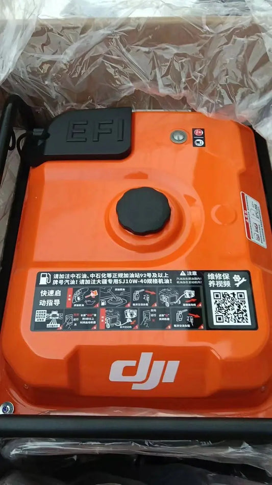
Operation panel
The engine switch starts or stops the generator. The USB-C port connects the remote controller for firmware update and log export. The AC outlet is IP44-rated according to the manual; reinstall and fasten the shield when it is not in use. The ground terminal is the connection point for proper grounding.
If the physical start/stop control itself is damaged, see the D14000iE Control Panel Switch Button. The broader electronic-control path includes the D14000iE Generator Controller.

Charging Channel Status LED
| Pattern | Meaning |
|---|---|
| Solid yellow | Battery connected and ready for charging |
| Green blink once continuously | Charging |
| Solid green | Fully charged |
| Yellow blink once continuously | Battery/charging-channel warning |
| Red blink once continuously | Battery/charging-channel error |
AC Module Status LED
Solid yellow means ready for use; a repeating green blink means in use; repeating yellow means warning; repeating red means error.
Generator Status LED
Four repeating yellow flashes mean not activated. A single repeating yellow flash is a warning. A single repeating red flash is a generator error. Four repeating red flashes mean generator maintenance is required.

Do not replace parts from LED color alone
An LED identifies the system branch, not the failed component. If diagnostics narrow a no-start condition to cranking hardware, exact active parts include the D14000iE Electric Starter and Starter Motor Relay. Capture the remote-controller message before selecting a part.
Parts & Equipment Referenced in This Guide
Shop Related D14000iE Collections
Related D14000iE Tutorials
Source and revision note
Primary source: DJI D14000iE Multifunctional Inverter Generator User Manual v1.0 (2025.06), pp. 7-9 and 12.