
DJI Agras T100 Tutorial: How to Install the DJI T100 4G Module
Share
DJI Agras T100 Tutorial: How to Install the DJI T100 4G Module
🇺🇸 U.S.A. FIRST — DJI Agras T100 4G Module Mounting, Signal-Cable Routing & Network Verification
The DJI Agras T100 4G Module installation is a compact modification with an unusually high dependency on mechanical detail. The module itself snaps into a dedicated base on the aircraft’s right middle frame, but successful installation also requires removal and correct reinstallation of two protected airframe areas, precise routing through multiple shell openings, a secure connection at the parameter-adjustment interface, and a final network check in the app.
The source procedure accounts for nine screws on the front cover, four screws on the power-distribution-board dust cover, four M3×8 screws for the 4G module base, the module’s upper M3×8 retaining hardware, and two screws at the parameter-adjustment interface. Losing the screw map, pinching the signal cable, leaving the power-distribution area open, or powering the aircraft before the interface is secure can convert a straightforward accessory installation into an aircraft fault.
This Ares Acres tutorial expands DJI’s official T100 4G Module Installation video into a complete technician-facing workflow. It covers power isolation, hardware control, front-cover removal, dust-cover access, base mounting, module retention, middle-frame handling, cable-holder engagement, bottom-to-top cable routing, parameter-interface connection, cover closure, app diagnostics, cellular-network validation, troubleshooting, and post-install inspection.
The 4G Module should be treated as a supported network accessory whose exact availability and functions can vary by country, carrier, account, app version, firmware, and DJI service status. It does not make every mission legal beyond visual line of sight, replace required command-and-control procedures, or eliminate the need for a healthy primary aircraft link.
Ares Acres supports DJI Agras operators with aircraft, OEM parts, connectivity equipment, diagnostics, technical education, and field-service resources. Explore the DJI Agras T100, DJI T100 Parts, DJI Agras Parts, DJI Accessories, the Ares Acres Product Catalog, or contact Ares Acres.
Prefer to watch instead of read? The video above demonstrates the physical installation sequence. Use this written guide to organize the thirteen outer-cover screws, preserve the power-distribution-board dust protection, route the signal cable without pinching it, secure the parameter-adjustment interface, and complete the app and network checks.
What You’ll Learn
- What the DJI T100 4G Module installation changes.
- What cellular connectivity can and cannot do for an agricultural-drone operation.
- Why the aircraft must be powered off and its battery removed.
- How to organize the nine front-cover screws.
- How to organize the four power-distribution-board dust-cover screws.
- How to remove the front cover without damaging clips, seals, or wiring.
- Where the 4G module base mounts on the right middle frame.
- How to install the base with four M3×8 screws.
- How to snap the 4G module into its base.
- How to install the upper M3×8 retaining hardware.
- How to open the middle-frame latch safely.
- How to lift the device body without pulling a cable or stressing the frame.
- How to snap the 4G module signal cable into its cable holder.
- How to route the signal cable from the bottom upward.
- Which lower-shell and middle-frame openings the cable passes through.
- How to loosen the two parameter-adjustment-interface screws.
- How to seat the signal cable in the interface.
- How to secure the interface and tidy cable slack.
- How to confirm the cable is not pinched by the body, latch, shell, or front cover.
- How to reinstall the front cover and tighten all nine screws progressively.
- How to reinstall all four power-distribution-board dust-cover screws.
- How to perform a complete closure and fastener audit.
- How to inspect the app for errors.
- How to verify that the 4G module’s network connection is normal.
- How to distinguish a mechanical-installation fault from a cellular-service fault.
- How to troubleshoot module recognition, network availability, and intermittent connection.
- Why 4G service does not automatically authorize BVLOS operations.
- How to document the modification for future service and diagnostics.
Quick Answer: How Do You Install the DJI T100 4G Module?
Power Off the T100 → Remove the Flight Battery → Organize Hardware → Remove Nine Front-Cover Screws → Remove Four Power-Distribution-Board Dust-Cover Screws → Remove Front Cover → Position 4G Module Base on Right Middle Frame → Install Four M3×8 Screws → Snap 4G Module Into Base → Tighten Upper M3×8 Retaining Hardware → Open Middle-Frame Latch → Lift Device Body → Snap Signal Cable Into Cable Holder → Route Cable Bottom-Up Through Device-Body Lower-Shell Opening → Continue Through Middle-Frame and Lower-Shell Openings → Loosen Two Parameter-Adjustment-Interface Screws → Insert Signal Cable Into Interface → Secure Both Interface Screws → Arrange Cable Slack → Check Every Pass-Through and Pinch Point → Snap Front Cover Into Place → Tighten Nine Front-Cover Screws Progressively → Tighten Four PDB Dust-Cover Screws → Reinstall Battery → Power On → Check App for Errors → Verify 4G Module Recognition and Normal Network Connection.
The two most important quality controls are cable routing and closure integrity. A correctly seated module can still fail if its cable is pulled, twisted, misaligned at the interface, or trapped under the body. A working network does not excuse a missing cover screw or an incompletely sealed power-distribution-board dust cover.
Installation Sequence at a Glance
| Phase | Main work | Completion evidence |
|---|---|---|
| Power isolation | Aircraft off, battery removed, work area controlled | No energy source installed; no accidental power-on risk |
| Cover access | Nine front-cover and four PDB dust-cover screws removed | Hardware mapped; cover removed without damage |
| Module mounting | Base secured to right middle frame; module snapped in | Base flush and stable; module fully retained |
| Cable routing | Signal cable clipped and routed bottom-up through openings | No twist, chafe, tension, or pinch point |
| Interface connection | Two interface screws loosened, connector inserted, screws secured | Connector seated squarely and retained |
| Closure | Front cover and PDB dust cover reinstalled | All thirteen outer-cover screws present and even |
| Verification | Aircraft powered on, app checked, network tested | No related errors; normal 4G connection displayed |
What the DJI T100 4G Module Does
The 4G Module provides a supported cellular-network connection for compatible DJI Agras T100 functions in regions where the hardware, service, carrier, and firmware are available. Depending on the current DJI implementation, a cellular path may support network-dependent features or add resilience to data transmission.
Because the exact feature set can change, use the controller and current DJI documentation as the authority. Do not assume that a function described for a DJI consumer or enterprise Cellular Dongle is identical on the T100.
DJI’s broader cellular-dongle guidance notes that performance depends on public 4G coverage, signal strength at the equipment, carrier base-station load, account status, app version, and firmware. Those principles are useful for diagnosis, but the T100-specific app prompts and documentation control this installation.
What the 4G Module Does Not Do
The module does not:
- repair a damaged primary transmission system;
- guarantee coverage in every field or at every altitude;
- overcome a carrier outage or congested tower;
- replace correct antennas, connectors, or signal-cable routing;
- make an unsupported SIM, carrier, or region compatible;
- authorize flight beyond the pilot’s actual approval;
- convert a Part 107 operation into a large-UAS authorization;
- eliminate the requirement to follow Part 91, Part 137, exemption, COA, or airspace conditions where applicable;
- make an aircraft safe to fly when the app reports a system fault; or
- justify closing the aircraft with a pinched cable or missing fastener.
4G Is a Connectivity Layer, Not a Regulatory Shortcut
A stronger or additional network path changes equipment capability, not legal authority. The FAA states that Part 107 applies to aircraft weighing less than 55 pounds at takeoff, while large agricultural UAS can require a different framework. Covered T100 dispensing operations may involve Part 91, Part 137, an exemption, aircraft registration, an Agricultural Aircraft Operator Certificate, a COA, and the limitations in the operator’s documents.
Review the FAA’s current Part 137 agricultural-UAS guidance and Section 44807 information. A cellular connection does not waive visual-line-of-sight, command-and-control, lost-link, crew, or operating-area requirements.
Hardware & Fastener Map
| Location | Hardware identified in source procedure | Purpose |
|---|---|---|
| Front cover | Nine screws | Secures front cover to aircraft body |
| PDB dust cover | Four screws | Secures protection over power-distribution-board area |
| 4G module base | Four M3×8 screws | Attaches base to right middle frame |
| Upper module retention | M3×8 screw(s) shown by DJI | Retains module/base assembly from above |
| Parameter-adjustment interface | Two screws | Secures 4G module signal-cable connector |
Do not infer that all screws are interchangeable because they appear similar. Keep every removed screw assigned to its original location. Use the kit-supplied M3×8 hardware only where DJI specifies M3×8.
Components Identified in the Installation
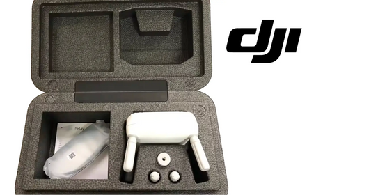
- DJI T100-compatible 4G Module;
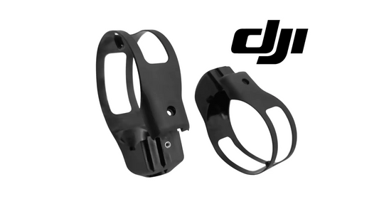
- 4G module base;
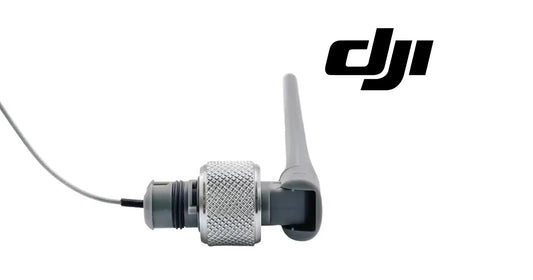
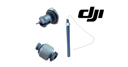
- 4G module signal cable;
- cable holder or integrated cable-retention point;
- four M3×8 base-mounting screws;
- upper M3×8 retaining hardware shown in the current kit;
- existing front cover and its nine screws;
- existing power-distribution-board dust cover and its four screws; and
- parameter-adjustment interface with two retaining screws.
Confirm the exact kit contents, module revision, aircraft compatibility, region, and current installation bulletin before disassembling the aircraft.
Required Tools & Work-Control Materials
Use the correct driver sizes specified by DJI for the aircraft and kit. The transcript identifies screw dimensions but not every driver type or every torque value, so do not invent either.
Recommended work-control materials include:
- correct non-damaging drivers for the front-cover, dust-cover, M3×8, and interface screws;
- low-range calibrated torque tool if the current service document specifies torque;
- magnetic-free or controlled hardware trays;
- labels for nine front-cover and four dust-cover screws;
- M3×8 kit-hardware tray;
- clean, dry, well-lit work surface;
- nonconductive inspection light;
- ESD-safe handling provisions appropriate for electronic modules;
- lint-free cleaning materials;
- camera or service log for before/after routing photos; and
- the current DJI T100 downloads and manuals.
Avoid loose metal objects near the power-distribution-board area. Do not use an oversized driver that can strip a screw or slip into the aircraft.
Before You Begin: Safety & Compatibility
Power State
- Land the aircraft on a stable service surface.
- Stop all motors and complete a normal shutdown.
- Power the aircraft off fully.
- Remove the flight battery.
- Keep the battery outside the immediate work area.
- Prevent another person from reinstalling a battery during the job.
- Do not connect or disconnect the module interface with the aircraft energized.
Work Environment
- Keep the aircraft dry and protected from blowing dust.
- Do not perform the installation in rain, mist, chemical spray, or high humidity that can condense inside the aircraft.
- Use enough light to inspect connector seating and cable openings.
- Keep liquids and conductive debris away from the open PDB area.
- Support the aircraft so opening the middle-frame latch cannot make it shift or collapse.
Electronic Handling
- Handle the module by its housing, not by pulling the cable.
- Do not touch connector contacts unnecessarily.
- Do not bend, crush, sharply fold, twist, or stretch the signal cable.
- Do not force a keyed connector into the parameter-adjustment interface.
- Protect the interface from dirt while it is open.
Compatibility Gate
Verify:
- aircraft is a compatible DJI Agras T100 revision;
- module and base are intended for that aircraft and region;
- signal cable matches the module and aircraft interface;
- current firmware supports the accessory;
- required network service is available in the region;
- any required account, subscription, carrier, SIM, or APN setup has been completed according to current DJI instructions; and
- no aircraft damage makes the installation unsafe.
Do not use generic cellular-dongle instructions to modify the T100 unless DJI explicitly directs you to do so.
Step 1 — Prepare the Aircraft and Work Area
Place the folded or service-configured T100 on a stable surface with enough clearance to remove the front cover, reach the right middle frame, and lift the device body as shown by DJI.
Photograph the original cover fit, cable openings, and screw positions before removal. These images become useful references during closure.
Step 2 — Power Off the Aircraft
Confirm the aircraft is fully powered down. Wait for indicators and fans to stop as required by the current DJI procedure.
Step 3 — Remove the Flight Battery
Remove the battery and place it in a safe battery area. Physically verify that no power source remains installed before opening any cover.
Step 4 — Create a Hardware Map
Prepare separate labeled locations for:
- Front Cover 1–9;
- PDB Dust Cover 1–4;
- 4G Base M3×8 1–4;
- upper M3×8 retention hardware; and
- interface screws, if they are not captive.
Mapping screws prevents a similar-looking fastener from being installed in the wrong depth or location.
Step 5 — Inspect the Front Cover Before Removal
Check for cracks, gaps, missing hardware, deformation, residue, or prior cable pinching. If the cover is already damaged, document and correct the issue rather than treating it as part of the new installation.
Step 6 — Loosen the Nine Front-Cover Screws
Unscrew the nine screws securing the front cover.
Use a progressive pattern rather than fully removing one corner while the opposite side remains tight. Support the cover so it does not flex as tension is released.
Step 7 — Store the Nine Front-Cover Screws
Place each screw in its mapped position. Count all nine before proceeding.
If one screw differs in length, shoulder, washer, or finish, preserve its exact original location.
Step 8 — Loosen the Four PDB Dust-Cover Screws
Unscrew the four screws securing the dust cover over the power-distribution-board area.
Do not allow a tool or loose screw to fall into the open electrical area.
Step 9 — Store the Four Dust-Cover Screws
Place all four in their dedicated tray. Keep them separate from the nine front-cover screws.
The outer-cover audit now accounts for thirteen removed screws.
Step 10 — Remove the Front Cover
Release the front cover carefully. Do not pry aggressively or pull it away before confirming that every screw and clip is free.
Observe how the cover edges, tabs, seals, and surrounding shells overlap. The same geometry must be restored during reinstallation.
Step 11 — Protect the Open Aircraft
Keep the exposed area clean and dry. Do not place the removed cover face-down on a surface that can scratch it or contaminate its sealing surfaces.
Step 12 — Locate the Right Middle-Frame Mounting Position
Identify the dedicated 4G module base location on the right middle frame shown in the DJI tutorial.
Confirm the mounting holes align naturally. If the base requires bending, drilling, enlargement, or forced alignment, stop and verify compatibility.
Step 13 — Orient the 4G Module Base
Position the base in the same orientation shown by DJI. Correct orientation determines how the module snaps in, where the upper retaining hardware fits, and how the signal cable reaches its holder.
Step 14 — Start the Four M3×8 Base Screws
Install the four M3×8 screws through the module base into the right middle frame.
Start all four by hand or with minimal driver force before final tightening. This allows the base to self-align without cross-threading.
Step 15 — Tighten the Four M3×8 Base Screws Progressively
Tighten the screws in an alternating pattern so the base seats evenly.
Use the torque specified in the current DJI installation documentation if one is provided. The video transcript does not supply a torque value, so do not guess or apply a generic aircraft torque.
Step 16 — Inspect the Installed Base
Confirm the base:
- sits flush against the right middle frame;
- does not rock or twist;
- has all four M3×8 screws present;
- does not interfere with the latch or nearby structure; and
- presents the module snap features in the correct direction.
Step 17 — Inspect the 4G Module
Before insertion, check the housing, snap features, cable connection, and signal cable for damage. Do not install a module with a cracked case, damaged connector, exposed conductor, or sharply creased cable.
Step 18 — Snap the 4G Module Into the Base
Align the module with the base and press it into place until the retaining features engage.
Do not press on the signal cable or use the cable to pull the module into position.
Step 19 — Perform a Module Retention Check
Apply a gentle housing-only check in the directions the module could move during vibration. It should remain fully seated without lifting from the base.
If it moves, remove and inspect the module and base rather than relying on the upper screw to force an incomplete snap connection.
Step 20 — Install the Upper M3×8 Retaining Hardware
Install and tighten the upper M3×8 screw or screws shown for the current kit.
Use the exact quantity supplied and identified by the current DJI instructions. The source narration refers to M3×8 hardware on top but does not provide a reliable count, so the kit and official diagram control.
Step 21 — Inspect Module Clearance
Confirm the secured module does not contact a moving latch, cover edge, sharp structure, or other cable. Check that its signal-cable exit follows the intended direction without a tight bend.
Step 22 — Open the Middle-Frame Latch
Release the middle-frame latch according to the T100 procedure. Keep fingers clear of closing and hinge points.
Verify the aircraft is supported before the body is lifted.
Step 23 — Lift the Device Body
Lift the device body only as shown by DJI and only enough to access the cable-routing path.
Do not lift by a cable, antenna, cover, tank connection, or unsupported shell. Watch every existing harness as the body moves.
Step 24 — Identify the Signal-Cable Holder
Locate the dedicated cable holder for the 4G module signal cable. The holder prevents the cable from moving into the latch, cover edge, or other service area.
Step 25 — Snap the Signal Cable Into the Holder
Press the cable into the holder at the designated section. Confirm the holder captures the cable without crushing its insulation.
Leave enough controlled slack for the module and body geometry, but not enough for a free loop to rub or snag.
Step 26 — Locate the Device-Body Lower-Shell Cable Opening
Identify the first lower-shell opening in the routing sequence. Inspect it for debris, sharp damage, or an existing cable conflict.
Step 27 — Route the Signal Cable From Bottom to Top
Feed the signal cable from the bottom upward through the device-body lower-shell cable opening.
Maintain the connector’s natural orientation. Do not pull on the wires behind the connector or force it through at an angle.
Step 28 — Continue Through the Middle-Frame Opening
Guide the cable through the corresponding middle-frame opening. Confirm the cable is not crossing a latch path, structural edge, or moving interface.
Step 29 — Continue Through the Lower-Shell Opening
Route the cable through the next lower-shell opening identified by DJI. The completed path should follow the protected internal route shown in the tutorial.
Step 30 — Inspect All Cable Pass-Throughs
At each opening, verify:
- insulation is intact;
- connector has not been damaged;
- cable is not twisted;
- no sharp edge bears directly on the cable;
- existing harnesses are not displaced;
- cable does not obstruct closure; and
- enough slack remains for normal assembly without tension.
Step 31 — Locate the Parameter-Adjustment Interface
Find the parameter-adjustment interface and identify its two retaining screws. Confirm the port and connector match before loosening anything.
Step 32 — Loosen the Two Interface Screws
Loosen the two screws at the parameter-adjustment interface as shown by DJI.
If the screws are captive, leave them in the interface. If they are removable, place them in the mapped tray. Do not remove more hardware than the procedure requires.
Step 33 — Inspect the Signal-Cable Connector
Check keying, alignment features, pins, contacts, and strain relief. If the connector does not align squarely, do not rotate or force it blindly.
Step 34 — Insert the Signal Cable Into the Interface
Align the connector and insert it fully into the parameter-adjustment interface.
Use the connector body—not the cable—to apply insertion force. A properly keyed connector should seat squarely without excessive pressure.
Step 35 — Secure the Two Interface Screws
Tighten the two retaining screws progressively so the connector remains level. Do not fully tighten one side while the other side is visibly unseated.
Use DJI’s specified torque if supplied. Avoid overtightening the interface or stripping small hardware.
Step 36 — Perform an Interface Retention Check
Confirm the connector is flush, both screws are present, and gentle movement of the cable does not lift one side of the interface.
Never pull directly on the cable to perform an aggressive strength test.
Step 37 — Tidy the Signal Cable
Arrange cable slack along the intended path. The final cable should not:
- hang outside the shell;
- cross the middle-frame latch;
- touch a sharp or hot surface;
- rub a moving component;
- press against the PDB area;
- form a loop that can be trapped by the front cover; or
- place continuous tension on the module or interface.
Step 38 — Lower the Device Body Carefully
Return the device body to its normal position while watching the complete cable route. Stop immediately if the cable moves, tightens, buckles, or approaches a pinch point.
Step 39 — Lock the Middle-Frame Latch
Close and secure the middle-frame latch according to the current T100 procedure.
Confirm the latch reaches its fully locked position without pressing on the new cable.
Step 40 — Perform a Pre-Closure Cable Audit
Before reinstalling the front cover, trace the cable visually and by reference photos from:
- 4G module;
- cable holder;
- device-body lower-shell opening;
- middle-frame opening;
- next lower-shell opening; and
- parameter-adjustment interface.
This is the last convenient opportunity to correct routing.
Step 41 — Inspect Cover Mating Surfaces
Clean dry dust or debris from the front-cover and PDB-dust-cover mating surfaces using an approved method. Confirm seals, clips, edges, and holes are undamaged.
Do not introduce liquid cleaner into the open aircraft.
Step 42 — Snap the Front Cover Into Place
Align the front cover and engage its clips or locating features. The cover should sit naturally without a bulge.
If it will not sit flush, remove it and inspect the cable route. Do not use the nine screws to compress a trapped cable.
Step 43 — Start All Nine Front-Cover Screws
Install all nine front-cover screws loosely in their original positions.
Starting all nine before final tightening helps confirm that the cover is aligned and that no hole is being forced into position.
Step 44 — Tighten the Nine Front-Cover Screws One by One
Tighten the nine screws progressively in a distributed pattern. Watch the cover gap as each screw seats.
Use the current DJI torque specification if provided. Do not guess, overtighten, or continue turning a screw that is cross-threaded.
Step 45 — Audit the Front Cover
Confirm:
- nine screws are installed;
- screw heads sit correctly;
- cover gaps are even;
- clips are engaged;
- no cable is visible at the seam; and
- the cover is not cracked or distorted.
Step 46 — Reposition the PDB Dust Cover
Align the power-distribution-board dust cover with its original sealing surface and holes. Ensure no foreign object or cable sits under it.
Step 47 — Start the Four PDB Dust-Cover Screws
Install all four screws loosely in their mapped positions before final tightening.
Step 48 — Tighten the Four PDB Dust-Cover Screws
Tighten the four screws progressively so the dust cover seats evenly over the power-distribution-board area.
Step 49 — Audit the PDB Dust Cover
Confirm all four screws are present and the cover has no lifted edge, gap, crack, pinched seal, or trapped debris.
Dust-cover closure protects a critical electrical area and is part of the installation—not an optional cosmetic step.
Step 50 — Reconcile Every Fastener
The final hardware count should account for:
- nine front-cover screws installed;
- four PDB dust-cover screws installed;
- four M3×8 module-base screws installed;
- upper M3×8 retaining hardware installed as specified; and
- two parameter-interface screws secured.
No removed or kit fastener should remain unexplained.
Step 51 — Inspect the Complete Aircraft
Check the middle-frame latch, module retention, cover fit, nearby antennas, existing cables, body position, and all areas touched during service.
Verify that no tool, screw, tray, protective material, or loose part remains on or inside the aircraft.
Step 52 — Reinstall a Serviceable Battery
Only after mechanical closure and the complete hardware audit should a compatible, serviceable battery be installed.
Step 53 — Establish a Controlled Power-On Area
Keep propellers clear of people and objects. Do not perform the first power-on in a location where an unexpected warning, reboot, or network delay pressures the technician to rush.
Step 54 — Power On the Aircraft and Remote Controller
Use the normal DJI startup sequence. Allow the aircraft, controller, app, and module enough time to initialize.
Do not interpret a cellular status immediately before the system has completed startup.
Step 55 — Check the App for Errors
Review the controller app for:
- module-recognition errors;
- accessory or parameter-interface errors;
- communication warnings;
- firmware mismatch;
- network unavailable status;
- aircraft system warnings; and
- any new fault that appeared after installation.
Do not clear, dismiss, or fly through an unexplained error.
Step 56 — Confirm 4G Module Recognition
Verify that the app shows the module as installed or available in the supported status location. The exact menu, icon, or label can vary with app and firmware version.
Use the current T100 app prompt rather than a menu path from another DJI product.
Step 57 — Verify Normal 4G Network Connection
Confirm the app reports a normal cellular-network connection.
Where the regional configuration requires carrier, SIM, subscription, or APN setup, verify that those items are active according to the current DJI and carrier instructions.
Step 58 — Observe Connection Stability
Allow the system to remain powered in a safe stationary condition long enough to identify repeated connection and disconnection, delayed registration, or intermittent error messages.
Network bars or an icon alone do not prove stable data service.
Step 59 — Check for Firmware or Accessory Prompts
If the app requires a supported firmware update or accessory activation, follow the current DJI instructions with adequate battery and network power. Do not interrupt an update once it has begun unless DJI explicitly directs otherwise.
Step 60 — Complete a No-Flight Functional Review
Before considering flight, confirm:
- no app errors remain;
- module stays recognized;
- network status remains normal;
- primary control and video link remain normal;
- RTK/GNSS and other aircraft systems are not affected;
- covers remain seated; and
- module and cable area show no abnormal heat, movement, or noise.
Step 61 — Complete the Preflight Inspection
Perform the complete T100 preflight checklist. Installing a 4G module does not replace checks of propellers, arms, motors, landing gear, payload, battery, sensors, RTK, primary transmission, weather, airspace, and operating authority.
Use the DJI T100/T50 Pre-Flight Safety Tutorial as a companion reference.
Step 62 — Document the Installation
Record:
- aircraft model and serial/registration reference;
- 4G module part or serial identifier when available;
- module and kit revision;
- installation date;
- technician;
- firmware and app versions;
- carrier/service information where applicable;
- photos of base mounting, cable route, interface, and cover closure;
- app recognition result;
- network verification result; and
- any corrective action taken.
Detailed Cable-Routing Guide
| Routing point | Correct condition | Fault to prevent |
|---|---|---|
| Module exit | Natural bend and supported direction | Sharp fold or cable used as handle |
| Cable holder | Cable captured without crushing | Loose loop or damaged insulation |
| First lower-shell opening | Cable routed bottom-up | Reversed path or connector forced sideways |
| Middle-frame opening | Clear of latch and structure | Pinch, rub, or moving-frame interference |
| Next lower-shell opening | Protected internal route | Cable outside cover envelope |
| Parameter interface | Connector square and fully seated | Bent pins, partial insertion, one-sided gap |
| Final slack | Controlled and serviceable | Tension at connector or loose snagging loop |
Why Bottom-to-Top Routing Matters
The specified routing direction places the connector and cable through the shell geometry in the intended order. Reversing the path can create the wrong bend radius, leave excess cable in the module area, or prevent the connector from passing cleanly through an opening.
The route also protects the cable from service motion. When the body is lifted or lowered, a correctly retained cable should not enter the latch or become the structural stop.
Front-Cover Closure Standard
A completed front cover should have:
- all nine original screws;
- even seams;
- correct clip engagement;
- no bulge over the cable;
- no exposed wire or insulation;
- no crack around a screw boss; and
- no movement when checked gently.
If a screw spins without seating, sits higher than the others, or requires abnormal force, stop and inspect the threads and hole alignment.
Power-Distribution-Board Dust-Cover Standard
The PDB dust cover should have:
- all four screws;
- an even perimeter;
- clean mating surfaces;
- no foreign material below it;
- no pinched seal or cable;
- no crack or distortion; and
- no missing protection after the app test.
Never leave the PDB area open because network verification is “temporary.” The aircraft should be fully closed before power-on unless a current DJI diagnostic procedure explicitly requires otherwise.
App and Network Verification Checklist
| Check | Pass condition |
|---|---|
| Aircraft boot | Normal initialization without new aircraft fault |
| Module detection | T100 app identifies or displays supported 4G status |
| Parameter interface | No connector or accessory communication error |
| Firmware | Compatible versions; no unresolved mismatch prompt |
| Service/account | Required regional service is active |
| Cellular registration | App shows normal network availability |
| Stability | Status remains connected without repeated cycling |
| Primary link | Normal controller/video operation remains available |
| Other systems | No unintended RTK, payload, battery, or sensor warning |
Mechanical Fault vs. Network Fault
Likely Mechanical or Installation Fault
Suspect installation when:
- module is not detected at all;
- status changes when the body or cable is moved;
- the interface reports a hardware fault;
- a connector is visibly uneven;
- module housing is loose in the base;
- front cover will not sit flush;
- cable is pinched or sharply bent; or
- error appeared immediately after installation.
Power down and remove the battery before reopening the aircraft.
Likely Service or Network Fault
Suspect network provisioning or coverage when:
- module is recognized but service is unavailable;
- connection changes with location while hardware remains stable;
- account, subscription, SIM, carrier, APN, or regional service is not active;
- local carrier coverage is poor or congested;
- app indicates network authentication rather than module hardware failure; or
- a known carrier outage is present.
Do not reopen the aircraft repeatedly when the app clearly recognizes the module and reports a service-side issue.
Common DJI T100 4G Module Installation Mistakes
1. Working With the Battery Installed
Opening covers and connecting the parameter interface on an energized aircraft creates unnecessary electrical and accidental-start risk.
2. Mixing the Thirteen Outer-Cover Screws
Nine front-cover and four PDB dust-cover screws should remain mapped separately.
3. Assuming Every M3×8 Screw Has the Same Role
Use the four base screws and upper retaining hardware only in the positions DJI specifies.
4. Mounting the Base Backward
Incorrect base orientation can misdirect the module, top retention, and cable exit.
5. Tightening One Base Screw Fully Before Starting the Others
This can pull the base out of alignment or cross-thread another hole.
6. Forcing the Module Instead of Engaging the Snap Features
The module should align with the base before retention hardware is tightened.
7. Using the Signal Cable as a Handle
Pulling the module by its cable can damage the strain relief or internal conductor.
8. Lifting the Device Body Without Supporting the Aircraft
The frame or body can shift, close, or stress existing harnesses.
9. Skipping the Cable Holder
An unsecured cable can migrate into the latch or cover seam.
10. Routing From the Wrong Direction
The source procedure specifies bottom-to-top routing through the lower-shell opening.
11. Crossing the Middle-Frame Latch
The cable may be cut, crushed, or tensioned when the latch closes.
12. Forcing the Connector Into the Interface
A keyed connector that is misaligned can damage pins or the port.
13. Tightening One Interface Screw While the Other Side Is Raised
The connector can remain partially seated or become mechanically skewed.
14. Leaving Excess Cable Loose
A free loop can rub, snag, interfere with the cover, or transfer vibration to the connector.
15. Using the Cover Screws to Flatten a Bulge
A bulging front cover often indicates a trapped cable or misaligned clip.
16. Forgetting One of the Nine Front-Cover Screws
An incomplete fastener pattern can allow movement, gaps, or unequal stress.
17. Leaving the PDB Dust Cover Incompletely Secured
All four screws and the full perimeter need inspection.
18. Guessing Torque
The transcript does not provide torque values. Use current DJI service data rather than a generic value.
19. Powering On Before Hardware Reconciliation
An unexplained screw could be inside the aircraft.
20. Treating Network Bars as the Only Test
Recognition, stability, app errors, service status, and the primary link also need verification.
21. Assuming a Carrier SIM Works Because It Works in a Phone
Compatibility, provisioning, APN, PIN, account, region, and DJI support can differ. Follow T100-specific guidance.
22. Installing Consumer-Drone Cellular Instructions on the T100
Menu names, module revisions, services, and antenna architecture may differ.
23. Flying With an Unexplained App Warning
No network benefit justifies flight with an unresolved aircraft or accessory fault.
24. Treating 4G as BVLOS Authorization
Network capability does not modify FAA approval or operating limitations.
Troubleshooting the DJI T100 4G Module
| Symptom | Likely cause | Safe corrective action |
|---|---|---|
| Module not shown in app | Interface not seated, cable damaged, incompatible kit, or firmware mismatch | Power down, remove battery, inspect module, full cable route, and interface; verify compatibility and firmware. |
| New parameter-interface error | Connector uneven or retaining screws not secured | Power down and reseat the connector squarely. |
| Status changes when body is moved | Cable tension, pinch point, or damaged conductor | Stop testing; reopen and correct routing before further power-on. |
| Module moves in base | Snap features or upper M3×8 retention incomplete | Power down and reinstall module/base correctly. |
| Front cover will not sit flush | Cable, clip, seal, or wrong screw alignment | Remove cover and correct the obstruction; do not compress it with screws. |
| PDB dust-cover gap | Debris, misalignment, cable intrusion, or uneven tightening | Power down, remove battery, inspect and reseat the cover. |
| Module recognized but no network | Coverage, service, carrier, SIM, APN, PIN, subscription, or region issue | Follow the app and current DJI/carrier provisioning guidance. |
| Network connects then drops | Weak coverage, congestion, account issue, cable fault, or firmware | Compare stationary locations, app errors, and hardware stability before reopening. |
| App requests update | Accessory/aircraft/controller firmware not aligned | Use adequate power and follow the current DJI update procedure. |
| 4G icon unavailable after startup | Initialization delay, module not detected, or service unavailable | Wait the required initialization period, then follow the T100 app diagnostic prompt. |
| Network normal but video/control poor | Primary transmission or site issue | Diagnose the primary link; do not assume 4G replaces it. |
| Aircraft reports unrelated error | Existing harness displaced or body/cover reassembly issue | Power down and inspect every area disturbed during installation. |
If the Module Is Not Recognized
Use this order:
- record the exact app message;
- power down fully;
- remove the battery;
- verify module compatibility and orientation;
- confirm module is snapped into the base;
- inspect upper retention;
- trace the cable through every opening;
- inspect for pinch, abrasion, or tension;
- verify the parameter-interface connector is square;
- verify both interface screws are secure;
- inspect whether another harness was disturbed;
- close all covers correctly;
- reinstall the battery and restart;
- check required firmware; and
- stop and seek DJI or Ares Acres support if the fault remains.
Do not perform repeated live reconnect attempts at an open interface.
If the Module Is Recognized but the Network Is Unavailable
Use this order:
- confirm regional T100 4G service is supported;
- confirm required carrier or service activation;
- verify any SIM or account status under current DJI instructions;
- verify any required PIN or APN setup;
- check local carrier coverage and outage information;
- allow complete system initialization;
- review the app’s network troubleshooting prompt;
- confirm aircraft, controller, app, and accessory firmware compatibility;
- test stationary operation in a known supported coverage area; and
- contact DJI, the carrier, or Ares Acres with the recorded status.
Avoid changing multiple account and hardware variables simultaneously. A controlled diagnosis makes the actual cause easier to isolate.
Post-Installation Maintenance
Before Each Operation
- Confirm module/network status in the app.
- Confirm primary transmission is normal.
- Check for new accessory or firmware warnings.
- Visually inspect the front cover and PDB dust cover.
- Confirm the middle-frame latch is secure.
- Verify the module area has not been struck or loosened.
During Scheduled Service
- Review network drop or error history.
- Inspect cover gaps and screw retention.
- Inspect the module base for movement.
- Inspect accessible cable sections for chafe or chemical residue.
- Verify firmware and regional service status.
- Recheck carrier/account provisioning when service changes.
After Impact, Repair, or Deep Cleaning
Inspect the module, base, cable route, parameter interface, front cover, and PDB dust cover before returning the aircraft to service. Water pressure, chemical residue, frame movement, or a cover replacement can affect the installation even when the app initially shows a network icon.
Ares Acres Recommended Installation Workflow
- Confirm module, base, cable, aircraft, and region compatibility.
- Review the official DJI T100 installation video and current downloads.
- Confirm required network service and account prerequisites.
- Move the T100 to a clean, dry, stable service area.
- Power off and remove the battery.
- Photograph the original aircraft condition.
- Prepare separate hardware maps.
- Remove nine front-cover screws progressively.
- Remove four PDB dust-cover screws progressively.
- Remove and protect the front cover.
- Position the 4G base on the right middle frame.
- Start all four M3×8 base screws.
- Tighten the base evenly using current DJI specifications.
- Snap the module fully into the base.
- Install the upper M3×8 retaining hardware.
- Inspect module retention and cable exit.
- Support the aircraft and open the middle-frame latch.
- Lift the device body only as required.
- Snap the signal cable into its holder.
- Route the cable bottom-up through the first lower-shell opening.
- Continue through the middle-frame opening.
- Continue through the next lower-shell opening.
- Inspect every pass-through.
- Loosen the two parameter-interface screws.
- Insert the connector squarely.
- Tighten both interface screws progressively.
- Arrange slack and protect every pinch point.
- Lower the body while observing the cable.
- Lock the middle-frame latch.
- Trace the entire cable before closure.
- Snap the front cover into place.
- Start and progressively tighten all nine front-cover screws.
- Reinstall and tighten all four PDB dust-cover screws.
- Reconcile every removed and supplied fastener.
- Inspect all touched systems and remove tools.
- Install a serviceable battery.
- Power on in a controlled area.
- Check the app for all errors.
- confirm module recognition;
- verify normal 4G service and connection stability;
- complete firmware prompts under current DJI instructions;
- complete a no-flight systems review;
- complete the full T100 preflight; and
- document the modification and verification result.
Related DJI Agras Operator Academy Tutorials
- DJI T100/T50 Pre-Flight Safety Tutorial
- DJI Agras Remote Operation View for T100 and T50
- DJI Agras Remote Controller Activation for T100 and T50
- DJI T100 D-RTK 3 Setup, Linking and RTK Coordinates
- DJI Agras T100 Route Mode Field Planning and Task Execution
- DJI Agras T100 Fruit Tree Mapping Tutorial
- DJI Agras T100 Orchard Operations Safety and Fruit Tree Precautions
- DJI Agras T100 A-B Operation Mode Tutorial
- DJI Agras T100 Manual and Manual Plus Operations
FAQ: DJI Agras T100 4G Module Installation
What is the DJI T100 4G Module?
It is a compatible cellular-network accessory for supported T100 functions. Exact features depend on region, service, app, firmware, and current DJI implementation.
Where is the module installed?
Its base mounts on the right middle frame, and the module snaps into that base.
How many screws secure the front cover?
Nine screws secure the front cover in DJI’s installation procedure.
How many screws secure the PDB dust cover?
Four screws secure the power-distribution-board dust cover.
How many screws mount the 4G base?
Four M3×8 screws secure the base to the right middle frame.
How many upper retaining screws are used?
Use the exact M3×8 quantity supplied and shown in the current DJI kit instructions. The source narration does not provide a dependable count.
Should the battery be removed?
Yes. Power off and remove the battery before opening covers, routing the cable, or connecting the interface.
Can I install the module outdoors?
Use a clean, dry, stable, well-lit work environment protected from rain, chemical spray, condensation, and blowing dust.
Why should the screws be mapped?
Different locations may use different fastener geometry. Mapping prevents wrong-depth or wrong-location installation.
Can I use any M3×8 screw?
Use the DJI-supplied or DJI-specified hardware for the module base and upper retention. Matching dimensions alone do not prove identical material or design.
How does the module attach to the base?
Align and snap it into the base, verify retention, and then install the upper M3×8 retaining hardware.
Why is the middle-frame latch opened?
Opening it allows the device body to be lifted for access to the protected signal-cable route.
Where does the signal cable go first?
Snap it into the dedicated cable holder, then route it from the bottom upward through the device-body lower-shell opening.
What is the complete cable route?
From the module and holder, the cable passes bottom-up through the device-body lower-shell opening, through the middle-frame opening, through the next lower-shell opening, and into the parameter-adjustment interface.
Why must routing go bottom to top?
It follows DJI’s designed shell geometry and helps maintain the intended bend, slack, and protected path.
How many screws secure the parameter interface?
Two screws secure the cable connector at the parameter-adjustment interface.
Should the interface screws be removed completely?
Loosen them as shown by DJI. If they are captive, keep them in place; do not remove more hardware than required.
How do I know the connector is seated?
It should align squarely, sit flush, and remain even as both retaining screws are tightened progressively.
How much cable slack should remain?
Enough to avoid tension through normal body and cover geometry, but not enough to form a loop that can rub, snag, or become pinched.
What if the front cover will not sit flat?
Remove it and inspect the cable, clips, seals, and alignment. Do not use the screws to force the cover over an obstruction.
Why is the PDB dust cover important?
It protects a critical electrical area. All four screws and the full perimeter must be correctly seated before service.
What should I check before installing the battery?
Reconcile all hardware, verify the cable route, lock the middle-frame latch, inspect both covers, and confirm no tool or loose part remains.
What is the first app check after power-on?
Review the entire app for new aircraft, accessory, interface, firmware, or network errors.
How do I verify the module?
Confirm the T100 app recognizes the accessory and reports normal cellular-network status in the current supported interface.
What if the module is recognized but has no network?
Check regional support, service/account status, carrier coverage, and any required SIM, APN, or PIN setup under current DJI instructions.
Can I use any SIM card?
Do not assume compatibility. Use the carrier, SIM type, provisioning, and setup supported for the T100 module in your region.
Does the 4G Module replace the primary radio link?
No. Maintain a healthy primary command, control, and video system and follow the current DJI lost-link procedure.
Does 4G guarantee connectivity everywhere?
No. Coverage depends on the carrier network, terrain, tower geometry, congestion, service status, and equipment condition.
Does the module permit BVLOS flight?
No. Equipment capability does not expand FAA authority, visual-observation requirements, or operating limitations.
Does Part 107 alone authorize T100 operations?
No. Part 107 applies below 55 pounds at takeoff. The T100 requires the large-UAS authority applicable to the mission, with Part 137 requirements for covered agricultural dispensing.
Should firmware be checked after installation?
Yes. Resolve supported accessory, aircraft, controller, and app version requirements before flight.
Can I fly if the network works but the app shows another error?
No. Diagnose every unexplained aircraft or accessory error before flight.
What records should I keep?
Record module identity, installation date, technician, hardware/firmware versions, routing photos, app recognition, network result, and any repair or corrective action.
Final Takeaway
The DJI T100 4G Module installation succeeds only when the aircraft is mechanically complete and electronically healthy. Begin with the battery removed. Keep the nine front-cover screws, four PDB dust-cover screws, four M3×8 base screws, upper retaining hardware, and two interface screws organized by location.
Mount the base to the right middle frame, snap and retain the module, open the middle-frame latch, lift the device body, and route the signal cable from bottom to top through the exact shell and frame openings. Seat the connector squarely in the parameter-adjustment interface, secure both screws, control the cable slack, and verify that closing the body and latch does not create a pinch point.
Closure is part of the installation: all nine front-cover screws and all four PDB dust-cover screws must be present and evenly seated. Only then should the battery be installed and the aircraft powered on. Check every app warning, confirm module recognition, verify normal and stable 4G network service, resolve firmware prompts, and complete the normal T100 preflight.
The module can strengthen supported network functionality, but it does not repair a weak primary link or expand legal operating authority. Compatibility, service availability, command-and-control procedures, and FAA limitations still apply.
Complementary DJI T100 Connectivity, Power & Service Equipment
Reliable T100 connectivity depends on the aircraft, controller, primary transmission system, 4G module, signal cable, positioning equipment, batteries, charging system, and correctly installed OEM hardware.
- DJI Agras T100 Aircraft — explore the T100 agricultural platform.
- DJI T100 OEM Parts — browse model-specific electronic, structural, spray, propulsion, and connectivity components.
- DJI Agras Parts — search the complete agricultural-drone parts catalog.
- DJI Agras Accessories — review compatible communications, positioning, and operational accessories.
- Ares Acres Product Catalog — search aircraft, batteries, charging equipment, modules, signal hardware, spreading systems, and air-seeder equipment.
- Ares Acres Technical Support — contact our team for T100 module compatibility, installation, part identification, or network troubleshooting.
What Is Ares Acres?
Ares Acres is a U.S.-based agricultural robotics company focused on DJI Agras aircraft, OEM parts, diagnostics, operator support, and technical education. Our DJI Agriculture Tutorials library turns short installation videos into technician-ready procedures with hardware control, verification gates, troubleshooting, and complete system context.
Need a DJI T100 4G Module, Parts, or Installation Support?
Explore the DJI Agras T100, browse DJI T100 Parts, search DJI Agras Parts, or contact Ares Acres for help identifying the correct regional module, cable, mounting hardware, or aircraft component.
Installation, network, and regulatory note: Module design, mounting hardware, screw torque, cable routing, interface labeling, app menus, firmware, supported carriers, SIM or account requirements, APN setup, network services, and regional availability can change. Follow the latest official DJI T100 installation, user-manual, release-note, app, and carrier instructions. Keep the aircraft powered off with its battery removed during mechanical and electrical work unless an official diagnostic procedure explicitly requires otherwise. A 4G connection does not authorize BVLOS flight, replace the primary command-and-control link, or expand the operator’s FAA exemption, Part 91, Part 107, Part 137, COA, airspace, registration, or operating limitations.