
DJI T100 Spreading System Tutorial: How to Program the DJI Spreading System
Share
🇺🇸 U.S.A. FIRST — DJI Agras T100 Spreading Support from Ares Acres
Ares Acres supports commercial DJI Agras operators with agricultural aircraft, OEM replacement parts, spreading-system components, batteries, accessories, technical resources, and practical operator tutorials. This guide is part of the Ares Acres DJI Agriculture Tutorials library and is designed to turn a short video demonstration into a detailed field reference that an operator can return to during setup, calibration, troubleshooting, maintenance, and seasonal preparation.
This tutorial focuses on programming and operating the DJI Agras T100 spreading system: selecting the correct screw feeder or auger, replacing the feeder, zeroing the weighing system, creating a material profile, performing spreading calibration with an adequate material load, reinstalling the spreading disc, selecting the correct material template before flight, and preventing common causes of blockage or inaccurate flow. Operators looking for replacement hardware can also browse the DJI Agras T100 Parts, the broader DJI Agras Parts catalog, or DJI Accessories.
Important: menu names can vary slightly by firmware, region, controller software version, and aircraft configuration. Use the labels displayed on your own remote controller as the final authority. Always power down and secure the aircraft before placing hands near the feeder, motor, spinner, material-detection mechanism, or other moving components.
Watch the DJI T100 Spreading System Video Tutorial
Prefer to watch the procedure? Watch the complete DJI T100 spreading-system tutorial on YouTube. The written manual below expands the video into a more complete operator workflow, including why each step matters, what can go wrong, how to distinguish feeder problems from calibration problems, and how to maintain the system between jobs.
What You Will Learn
- How the DJI Agras T100 spreading system meters fertilizer, seed, and other compatible granular material.
- How the weighing sensor and material-detection sensor perform different jobs.
- How feeder speed influences material flow.
- How to choose among small, medium, large, and extra-large screw feeders or augers.
- How to remove and replace a T100 feeder safely.
- How to perform weighing-sensor tare calibration.
- How to remove the spreader disc before material-flow calibration.
- How to add a new spreading material profile on the remote controller.
- Why the demonstration calls for at least 20 kg of material during calibration.
- How to select the correct saved material template before a job.
- How to prevent foreign-material contamination, bridging, blockage, and misspreading.
- How to respond to cold-weather material-detection false alarms.
- How to diagnose an incorrect application rate without immediately replacing hardware.
- Which T100 spreading-system parts are most relevant when a component is actually damaged.
DJI Agras T100 Spreading System: The Basic Architecture
The spreading system is not simply a tank with a hole in the bottom. It is a controlled material-delivery system that attempts to move a measured quantity of granular product from the hopper to the field while the aircraft is moving. The result depends on several layers working together:
- Material storage: fertilizer, seed, feed, or another compatible material is held in the spreading tank.
- Weight measurement: a weighing sensor measures the mass of material remaining in the tank.
- Material-presence detection: the material-detection mechanism provides a second signal related to whether material is present at the relevant point in the delivery system.
- Metering: the screw feeder, commonly called the auger by operators and parts suppliers, physically meters material out of the tank.
- Drive: the feeder motor turns the screw feeder at a commanded speed.
- Distribution: the spinner or spreader disc receives the metered material and throws it outward to form the final spread pattern.
- Software control: the controller uses the selected material template, feeder model, calibration data, and flight parameters to determine how quickly the feeder should run.
That distinction is central to troubleshooting. A drone can have a perfectly functioning spinner disc but still under-apply because the feeder is not delivering enough product. It can also have the correct feeder flow but produce an unacceptable pattern because the distribution side is obstructed, damaged, or configured incorrectly. Treat flow rate and spread pattern as related but separate diagnostic questions.
What Materials Can the T100 Spreading System Handle?
The source tutorial describes compatible spreading material with particle diameters generally ranging from 0.5 mm to 10 mm, including materials such as fertilizers and seeds. That range should be treated as a system-level material-size envelope rather than a promise that every substance between 0.5 and 10 mm will flow equally well. Particle diameter is only one property that affects real-world spreading.
Operators should also evaluate:
- Bulk density: two materials of identical particle size can weigh very differently per unit volume.
- Shape: round granules may flow more freely than irregular, elongated, or angular particles.
- Surface texture: rough particles can produce more friction than smooth coated granules.
- Moisture: damp material may bridge or clump even if the nominal particle size is appropriate.
- Dust content: fines can accumulate around sensors, feeder surfaces, and the spinner assembly.
- Foreign matter: straw, woven-bag fibers, plastic, string, stones, or debris can obstruct the auger.
- Application rate: the pounds per acre or kilograms per hectare being requested may require a feeder with greater or lower practical throughput.
This is why the T100 should be calibrated to the actual material being used rather than relying only on the crop name printed on a seed bag or fertilizer label.
Auger vs. Screw Feeder: Two Names for the Same Operator Decision
DJI interfaces and documentation may use the term screw feeder, while many operators, technicians, suppliers, and parts listings use auger. In this guide the terms are used interchangeably when discussing the removable screw that meters granular material from the T100 hopper.
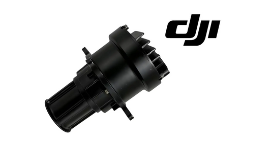
Ares Acres currently carries multiple T100 feeder sizes, including the DJI Agras T100 OEM Small Auger, DJI Agras T100 OEM Medium Auger, DJI Agras T100 OEM Large Auger, and DJI Agras T100 OEM Extra Large Auger. The feeder is not an accessory that should be chosen by the rule “larger is always better.” It is a metering component that should match the material and requested throughput.
T100 Feeder Size Reference: Small, Medium, Large, and Extra Large
The T100 SmartFarm feeder-selection interface provides useful operating ranges for feeder choice. These ranges are a starting point for setup, not a substitute for material calibration. Material shape, density, coating, moisture, flowability, flight speed, and environmental conditions can change actual performance.
| Feeder | Application-rate range | Material-size reference | General use logic |
|---|---|---|---|
| Small | 2.7–19.9 lb/acre | 0.5–4 mm | Lower-rate, finer-material applications. |
| Medium | 19.9–106.4 lb/acre | 4–6 mm | Intermediate throughput for compatible seed or granules. |
| Large | 66.5–239.3 lb/acre | 4–10 mm | Higher-rate applications and larger compatible particles. |
| Extra Large | 66.5–664.8 lb/acre | 0.5–10 mm | Very high-throughput applications when the material and mission require it. |
The source video simplifies this decision by explaining that a larger feeder is appropriate when the spreading amount is large and a smaller feeder when the spreading amount is small. That is a useful operational rule, but the table above shows why application rate and particle size should be considered together.
For a dedicated feeder-selection discussion, see the DJI Agras T100 Auger Size Guide.
Before You Begin: Safety and Setup Checklist
Before changing a feeder, removing the spinner disc, touching a sensor, or clearing a blockage, place the aircraft in a safe maintenance state. Never rely only on the assumption that a motor will not start.
- Land the aircraft on a stable surface.
- Disarm and power down the aircraft before placing hands near moving spreader hardware.
- Remove or isolate power when the procedure requires direct contact with the feeder, spinner, or sensor blades.
- Do not reach into a loaded hopper while the feeder can be energized.
- Use appropriate personal protective equipment for the agricultural material being handled.
- Keep fertilizer and seed dust away from electrical connectors.
- Verify that tools, pins, fasteners, and loose hardware cannot fall into the hopper.
- Do not perform calibration on unstable ground where aircraft movement can corrupt weighing measurements.
Operators who maintain their own fleets may also want the DJI Agras Universal Maintenance and Repair Tool System for organized field maintenance and service work.
Part 1 — How to Change the DJI T100 Screw Feeder / Auger
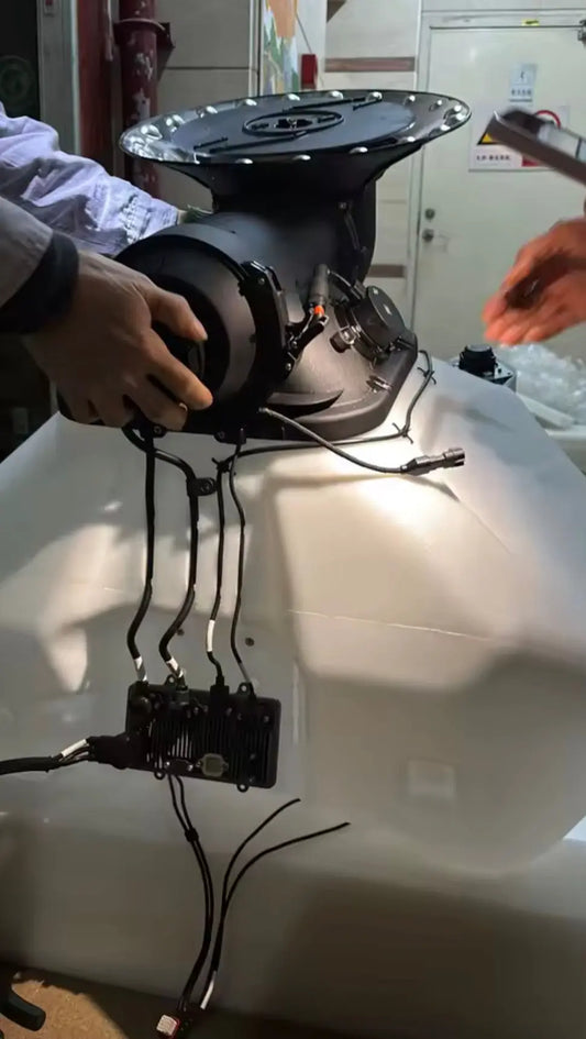
The tutorial demonstrates feeder replacement using a higher-rate fertilizer example. The objective is to physically install the feeder model that matches the intended material and throughput before calibrating the material profile. Calibrating one feeder and then flying with another defeats the purpose of the calibration.
Step 1: Confirm the feeder you intend to install
Before removing anything, identify the target material, its approximate particle size, the intended application rate, and the feeder size you plan to use. If you are switching from a low-rate seed application to a high-rate fertilizer application, the correct feeder may change substantially.
Step 2: Release the feeder motor lock
With the aircraft safely powered down for maintenance, release the feeder motor lock. This lock secures the motor to the auger interface. Do not force the motor free while the lock is still engaged; forcing locked components can damage the retention mechanism or misalign the drive interface.
Step 3: Remove the feeder motor
Remove the feeder motor carefully and support it rather than allowing it to hang from wiring or strike the aircraft. If the motor itself is damaged, noisy, intermittent, or unable to drive a known-good feeder, the current store listing for the replacement is the DJI Agras T100 OEM Auger Motor.
Step 4: Pull out the existing feeder
Remove the installed screw feeder from the metering path. Inspect the removed feeder for wear, cracked or distorted surfaces, packed fertilizer, sticky residue, foreign objects, or damaged bushings. If a feeder is difficult to remove, determine why rather than applying uncontrolled force.
Step 5: Install the appropriate feeder
Insert the feeder selected for the job. Verify that it seats correctly and is not obstructed. The feeder should not be treated as interchangeable without corresponding software configuration: the controller must later be told which feeder is installed.
Step 6: Reinstall the feeder motor in the correct orientation
The video specifically calls attention to feeder-motor orientation. Correct orientation matters because the motor must mate with the feeder drive and retention hardware as designed. Misorientation can produce poor engagement, inability to lock, abnormal noise, or a feeder that does not rotate correctly.
Step 7: Tighten and verify the feeder motor lock
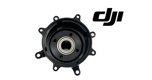
Secure the motor lock fully. Before loading material, visually inspect the assembly and verify there is no looseness that could change alignment under vibration. If the small-feeder support surface is worn, the DJI Agras T100 OEM Small Auger Bushing is one of the model-specific service components in the T100 catalog.
Why Changing the Feeder Requires Recalibration
A screw feeder meters material volumetrically and mechanically. Changing its geometry changes how much material can move per revolution and how the particles occupy the screw flights. Even if motor RPM remained identical, the mass flow could be different. That is why the software needs both the correct feeder identity and material-specific calibration.
Think of the control chain this way:
Target application rate → material template → feeder calibration → commanded feeder speed → actual mass flow → spinner distribution → field application.
If the feeder model in software does not match the feeder installed in hardware, the control system is starting with the wrong relationship between feeder rotation and material delivery.
Part 2 — Tare the T100 Weighing Sensor Before Material Calibration
After the feeder is installed, the video moves to spreading calibration and performs what the transcript calls “tear calibration.” In weighing terminology, the correct term is tare calibration: setting the empty spreading system to zero so the controller does not interpret the tank or hardware itself as payload material.
Step 1: Open Spreading System Settings
On the remote controller, enter the spreading-system settings. Depending on software version, labels may differ slightly.
Step 2: Select Spreading Calibration
Open the spreading-calibration function. This is where the weighing baseline and material-flow relationship are established.
Step 3: Perform Tare Calibration
Run tare calibration for the weighing sensor with the hopper in the required empty condition. The objective is for the controller to show a total spreading-tank weight of approximately 0 kg before material is added.
Step 4: Keep the aircraft level and mechanically stable
The video instructs the operator to elevate the aircraft and keep it level. This matters because the weighing system is measuring force. If the aircraft is being pushed, rocked, supported unevenly, or touched during the measurement, those external forces can be interpreted as changes in weight.
Why a Bad Tare Can Create a Bad Application Rate
A tare error does not stay isolated to the number shown on the screen. It can affect every calculation downstream that depends on measured material mass. If the system believes an empty tank contains material, or believes a partially loaded tank contains less material than it actually does, the calibration relationship can be distorted.
For that reason, if the displayed hopper weight does not return to zero when empty, do not immediately “work around” the problem by proceeding with calibration. First verify:
- the hopper is truly empty;
- nothing is pressing on or supporting the tank;
- the aircraft is level and stable;
- no material is jammed in a way that mechanically loads the weighing structure;
- the weighing hardware and connectors are intact;
- the controller is displaying the correct spreading system.
Part 3 — Remove the Spreader Disc for Flow Calibration
The calibration procedure shown in the video separates the metering measurement from final lateral spreading. Material needs to be collected below the aircraft so the system can establish the relationship between feeder operation and delivered material.
Step 1: Prepare a safe material-receiving container
Place an appropriate container below the spreading outlet before starting calibration. It should be large enough to capture the discharged material without allowing fertilizer or seed to scatter into motors, electrical components, or the work area.
Step 2: Remove the retaining pin
Remove the required pin from the spreader-disc assembly as demonstrated.
Step 3: Detach the spreader disc
Remove the spinner/spreader disc and store it in a clean location where it cannot be contaminated, stepped on, warped, or lost. Do not leave the disc beneath the aircraft during calibration.
Step 4: Inspect the disc while it is removed
Use the opportunity to inspect for cracks, unusual wear, packed residue, deformation, or evidence that the spinner has been contacting another component. The T100 catalog includes the DJI Agras T100 OEM Sowing Spinner Disc Shell and DJI Agras T100 OEM Spinner Disk Motor for cases where actual spinner hardware is damaged.
Part 4 — Create a New Spreading Material Profile
This is one of the most important programming steps. The T100 should not treat every fertilizer or seed as if it has the same density and flow behavior. A saved material profile lets the controller associate the installed feeder with calibration data for the actual material.
Step 1: Open Spreading Parameter Settings
From the spreading interface, open the spreading parameter settings.
Step 2: Open Spreading Material Management
Select the material-management function. This is where saved material templates can be created and selected.
Step 3: Select Add New Spreading Material
Create a new material profile rather than reusing an unrelated template simply because it appears close enough.
Step 4: Select the feeder that is physically installed
Choose the current feeder model in use and continue. This software selection should match the hardware you just installed. A mismatch between physical feeder and software feeder selection is a high-priority diagnostic item whenever the measured application rate seems impossible.
Step 5: Follow the remote-controller prompts
Add material and run the calibration exactly as prompted by the controller. Keep the aircraft stable throughout the process.
Why the Tutorial Requires at Least 20 kg of Material During Calibration
The source tutorial explicitly instructs the operator to use no less than 20 kg of material during spreading calibration. This is not a trivial detail. A meaningful calibration requires enough mass to produce a measurable, representative flow event. If only a very small amount of material is used, measurement noise, transient startup behavior, incomplete feeder filling, or irregular particle movement can represent too large a share of the total sample.
A larger calibration mass helps the system observe a more representative relationship between:
- feeder speed;
- time;
- measured mass change;
- material flow characteristics;
- the installed feeder geometry.
If the controller displays a material-shortage warning during calibration, the video instructs the operator to continue adding material and proceed with the calibration rather than prematurely ending the process.
Do Not Touch the Aircraft or Hopper During Calibration
This warning deserves its own section because it is easy to ignore. While the controller is using the weighing sensor, touching the aircraft or spreading tank adds external force to the measurement. Even a temporary push, lift, lean, or vibration can change the indicated mass and corrupt calibration.
During the active calibration measurement:
- do not lean on the aircraft;
- do not hold the spreading tank;
- do not move the landing gear;
- do not rest tools on the airframe;
- do not allow another person to stabilize the tank by hand;
- do not perform the procedure where strong vibration is being transmitted through the ground or support.
If you suspect the aircraft was disturbed during calibration, repeating the calibration is generally more sensible than trusting a questionable flow relationship and discovering the error over a field.
Part 5 — Save the Material Template and Reinstall the Spreader Disc
When calibration completes successfully, save the material profile. A useful fleet practice is to name material templates clearly enough that another operator can identify the exact material and feeder combination later. Avoid vague names such as “fertilizer 1” when the fleet may eventually carry many products.
A practical naming convention might include:
Material / formulation / feeder / season or revision
For example: Dry Granular Fertilizer – Large Feeder – 2026. The purpose is not administrative perfection; it is preventing an operator from accidentally selecting the wrong calibration profile during a time-sensitive job.
After saving, reinstall the spreader disc and its retention hardware exactly as required. The flow-calibration configuration is not the operating configuration. Before flight, visually verify the disc is installed, retained, free of obstruction, and ready to rotate.
Part 6 — Select the Correct Material Template Before Spreading
The video then moves from calibration into actual operation. In the flying-parameters panel, confirm that the correct material template is selected. This is one of the fastest checks an operator can make when a spreading system that worked yesterday appears to behave incorrectly today.
Before every job, verify three items together:
- Physical material: what is actually in the hopper?
- Physical feeder: which auger is actually installed?
- Software material template: which saved calibration is selected?
Those three should agree. If any one does not, stop and correct the configuration before treating the problem as a failed motor, sensor, or controller.
Part 7 — Install the Battery Before Loading Spreading Material
The source tutorial gives an important loading-order instruction: install the battery before adding spreading material. The stated reason is to reduce the chance that material contacts the distribution-board area during the battery installation process.
This is a good example of operational sequencing preventing an electrical problem. Granular fertilizer, seed treatments, dust, and debris do not belong on high-current or electronic interfaces. A protective component relevant to this area is the DJI Agras T100 OEM Distribution Board Protective Cover.
A practical load sequence is therefore:
- complete the aircraft inspection;
- install and secure the battery;
- verify the power/interface area is clean;
- only then load granular material into the spreading tank;
- close and secure the tank as required.
Part 8 — Screen the Material Before It Reaches the Auger
The video warns specifically about straw, woven-bag material, and clumped product. These can cause auger blockage and misspreading. In real agricultural operations, material contamination often comes from handling rather than from the product itself: torn bulk bags, fragments of twine, pallet debris, damp fertilizer, partially dissolved granules, or seed-treatment buildup.
Before loading:
- remove straw and plant residue;
- remove woven-bag strands, strings, plastic, paper, and packaging fragments;
- break apart clumps that are not representative of the intended particle size;
- do not load visibly wet or caked material merely because it can be forced into the tank;
- inspect the hopper and feeder inlet for material left from the previous job.
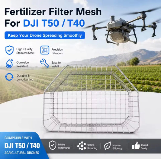
For operations that need another layer of screening, Ares Acres lists the DJI Agras T100 OEM Stainless Steel Fertilizer & Manure Spread Filter. The DJI Agras T100 OEM Dosing Tunnel with Filter is another relevant component in the metering path.
Understanding the Weighing Sensor vs. the Material-Detection Sensor
The tutorial describes two sensing functions that are easy to confuse.
Weighing sensor
The weighing system determines how much mass is being carried in the spreading tank. It is fundamentally a quantity measurement. It supports remaining-material estimation and calibration by observing changes in tank weight.
Material-detection sensor
The material-detection system helps determine whether material is actually present at the relevant delivery point. It is fundamentally a presence/flow-state signal rather than the primary tank-weight measurement.
These two signals complement one another. A hopper could show significant remaining weight while material is bridged above the feeder and not reaching the outlet. Conversely, a presence sensor can indicate that material is available without telling the controller the total amount remaining in the tank.
How the T100 Controls Spreading Flow
The core actuator is feeder speed. The spreading system can increase or decrease the screw-feeder rotation rate to change the amount of granular material being delivered. But commanded feeder speed is only useful when the controller has valid calibration data and the material can actually move through the hardware.
In simplified form:
Desired field rate + aircraft motion + material template → target mass flow → feeder-speed command.
The real material then passes through the feeder and onto the spinner disc. If the material is bridging, the feeder is obstructed, the wrong feeder is installed, the template is wrong, or the calibration is poor, commanded RPM and actual delivered mass can diverge.
Application Rate Is Not the Same as Spread Width
Operators sometimes adjust the wrong side of the system because both problems appear as “bad spreading.” Keep these concepts separate:
- Application rate is how much material is applied per unit of area. It is strongly influenced by metering flow, calibration, feeder selection, aircraft speed, and task settings.
- Spread width/pattern is how the metered material is distributed laterally. It is strongly influenced by spinner behavior, material characteristics, flight height, environmental conditions, and physical distribution hardware.
If the correct total mass leaves the hopper but the pattern is uneven, investigate the distribution side. If too little or too much total mass leaves the hopper, investigate the metering/calibration side first.
Cold-Weather Material Detection False Alarms
The video notes that in low-temperature regions, the material-detection sensor may fail to rotate freely, which can cause a false material alarm. The demonstrated response is to gently move the blades so that the mechanism can rotate normally.
Safety clarification: any manual movement of sensor blades or nearby spreading hardware should be performed only with the aircraft in a powered-down, de-energized maintenance state. Never place fingers near a component that could begin rotating under motor power.
If a false alarm appears in cold conditions:
- land and secure the aircraft;
- power down before touching the mechanism;
- inspect for ice, frozen moisture, packed dust, or material residue;
- verify the blades/mechanism can move freely without forcing them;
- remove contamination appropriately;
- restore power only after hands and tools are clear;
- confirm the alarm state again before flight.
If the mechanism remains abnormal after cleaning and temperature recovery, a sensor or associated hardware fault may be more likely. The live catalog includes the DJI Agras T100 OEM Auger Sensor.
Complete Pre-Operation T100 Spreading Checklist
- Verify the aircraft and spreading system are correctly installed.
- Inspect hopper, feeder, dosing tunnel, spinner disc, motors, locks, pins, and visible wiring.
- Confirm the correct auger is physically installed.
- Confirm feeder motor orientation and lock engagement.
- Verify weighing-system tare is reasonable when the tank is empty.
- Confirm the correct saved material profile exists.
- Confirm the selected material profile matches the installed feeder.
- Install and secure the aircraft battery before loading granular material.
- Inspect the distribution-board area and electrical interfaces for contamination.
- Screen material for straw, bag fibers, string, plastic, clumps, excessive moisture, and debris.
- Load the material without spilling it into electrical or mechanical areas.
- Verify material-detection hardware is free to move.
- Verify the spinner disc is reinstalled after calibration.
- Confirm the intended application rate and mission settings.
- Perform a small validation pass when using a new material or a newly calibrated profile.
T100 Spreading Troubleshooting Matrix
| Symptom | Likely areas to inspect first | Recommended first action |
|---|---|---|
| Empty hopper does not read 0 kg | Tare state, aircraft level, external load on tank, weighing hardware | Stabilize aircraft and repeat tare calibration. |
| Material shortage warning during calibration | Insufficient calibration mass | Add material; tutorial calls for at least 20 kg. |
| Material alarm despite material in tank | Material-detection sensor, cold temperature, bridging | Power down, inspect sensor movement and actual material path. |
| Auger does not rotate | Blockage, motor lock, motor, wiring, feeder alignment | Do not force it under power; de-energize and inspect the drive path. |
| Application rate consistently too low | Wrong feeder, wrong material template, poor calibration, bridging | Verify material/template/feeder match before replacing parts. |
| Application rate consistently too high | Wrong template, calibration error, incorrect feeder selection | Recheck profile and repeat calibration if necessary. |
| Rate changes erratically | Clumps, moisture, intermittent bridging, sensor instability | Inspect material quality and mechanical flow path. |
| Correct mass flow but poor field pattern | Spinner disc, spinner motor, material aerodynamics, operating height | Diagnose distribution hardware separately from metering flow. |
| Frequent auger blockage | Foreign debris, wet/clumped material, wrong feeder | Clean/screen material and confirm feeder suitability. |
| Calibration changes every time it is repeated | Aircraft movement, touching tank, inadequate sample, inconsistent material | Improve calibration conditions before assuming sensor failure. |
Diagnostic Workflow: Wrong Rate Before Buying Parts
When the spread rate is wrong, use a disciplined sequence:
- Confirm the material. Is the physical material the one you think is loaded?
- Confirm the feeder. Is small, medium, large, or XL actually installed?
- Confirm the software selection. Does the selected material template correspond to that feeder and material?
- Confirm tare. Does the empty hopper read approximately 0 kg?
- Inspect the material. Is it dry, free-flowing, and free of debris?
- Inspect the feeder. Is it clean and able to rotate without obstruction?
- Inspect the sensor mechanism. Is the material-detection mechanism moving normally?
- Repeat calibration correctly. Use the required quantity and avoid touching the aircraft.
- Perform a controlled validation test. Compare expected material use to actual material use.
- Only then isolate hardware. Determine whether the motor, sensor, feeder, dosing tunnel, spinner motor, or structural component is actually at fault.
This approach prevents a common service mistake: replacing a functional auger motor when the real problem is a wrong material template or a clumped fertilizer bridging above the feeder.
How to Validate Calibration in the Field
A calibration that completes successfully on the controller should still be validated operationally when the material is new or the feeder configuration changed. A practical field check compares the planned material consumption with the observed reduction in hopper mass over a known area.
If the discrepancy is meaningful, do not immediately compensate by randomly adjusting application parameters. First determine whether the cause is:
- calibration;
- wrong feeder profile;
- material behavior;
- bridging;
- mission speed/area assumptions;
- or a hardware problem.
The purpose of validation is to catch a system-level mismatch before it becomes a field-scale application error.
Multi-Material Operations: Do Not Treat Every Blend as the Same Product
Cover-crop blends, coated seed, fertilizer formulations, feed, and granular products may contain particles with significantly different density and geometry. A blend can also segregate during handling, allowing smaller particles to settle while larger particles remain higher in the hopper. The material may therefore flow differently from a single-species seed even when the average particle size appears similar.
For mixed materials:
- inspect the blend before loading;
- use the feeder that accommodates the most demanding relevant material characteristic;
- calibrate the actual blend rather than one individual component;
- watch for segregation and inconsistent flow;
- perform a small validation run before committing the entire acreage.
Maintenance After Every Spreading Job
Granular spreading is mechanically simple compared with some aircraft systems, but fertilizer and seed residues can be aggressive. Maintenance should focus on preventing residue from becoming tomorrow's blockage or corrosion source.
1. Empty unused material
Do not leave fertilizer or seed sitting in the tank indefinitely. Remove remaining product according to the material's handling requirements.
2. Clean the hopper
Remove fines, dust, clumps, treatment residue, and fragments of packaging. Pay attention to corners and transitions that can trap material.
3. Clean the auger and metering path
Inspect the screw feeder, bushing/support areas, dosing tunnel, and motor interface. Packed material can change drag and throughput.
4. Inspect the material-detection mechanism
Verify it is clean and free to move after the system is de-energized.
5. Inspect the spinner disc
Look for wear, cracks, deformation, packed residue, or an uneven surface that could change the spread pattern.
6. Inspect locks and pins
Feeder motor locks and spreader-disc retention hardware are small components with large operational consequences. Verify they are present and secure.
7. Keep electrical areas clean and dry
Avoid allowing granular material to accumulate around the distribution-board area, battery interface, connectors, or electronic modules.
8. Store the system dry
Moisture can turn free-flowing fertilizer into a solid mass and can accelerate corrosion. Clean, dry storage is part of spreading-system reliability.
Pre-Season Spreading System Inspection
Before cover-crop season or a major fertilizer window, inspect the spreading system before the first commercial job rather than discovering missing parts in the field.
- Inventory all feeder sizes required by the operation.
- Inspect the small, medium, large, and extra-large augers that the fleet intends to use.
- Inspect feeder bushings and shaft interfaces.
- Confirm the auger motor runs normally.
- Verify the auger/material sensor is clean and operational.
- Inspect the dosing tunnel with filter.
- Inspect the spinner disc and spinner disk motor.
- Review saved material templates and remove confusing duplicates only after preserving useful records.
- Perform tare verification and material calibration before the first high-value application.
- Make sure operators know which feeder/template combination is approved for each recurring material.
Fleet Management: Standardize Material Profiles Across Multiple T100s
For multi-aircraft operations, the biggest risk is often inconsistency between aircraft rather than ignorance of the procedure. One pilot may call a material “Urea,” another “Fert,” and another “White Granular,” while using different feeders and calibrations. Create a fleet standard.
For each recurring material, record:
- material name and formulation;
- supplier/product identifier;
- approximate particle-size range;
- feeder size;
- date of calibration;
- aircraft or spreading-system identifier;
- application-rate range actually used;
- operator notes about flowability or clumping;
- any deviations observed during validation.
This turns spreading calibration from an individual pilot memory into a repeatable fleet process.
Common Operator Mistakes
- Using the largest auger for everything. Greater maximum throughput is not the same as better metering at every application rate.
- Changing feeders without changing the software selection.
- Reusing an old material profile for a materially different product.
- Skipping tare because the displayed weight “looks close enough.”
- Calibrating with too little material.
- Touching or stabilizing the hopper during weighing calibration.
- Forgetting to reinstall the spreader disc after calibration.
- Loading material before the battery and contaminating an electrical area.
- Dumping a torn bulk bag directly into the hopper without screening fibers or debris.
- Trying to clear a blockage while the system is energized.
- Assuming every “material shortage” alarm means the hopper is empty.
- Assuming every poor spread pattern is an auger problem.
- Ignoring moisture because the particle diameter is technically in range.
- Failing to validate a new calibration before treating a large acreage.
When Is the Auger Motor Actually a Reasonable Suspect?
The motor becomes a more reasonable suspect when a known-clean, correctly installed feeder will not rotate; the motor produces abnormal noise; the motor cannot drive multiple known-good feeders; the problem follows the motor rather than the material; or the controller reports a motor-specific fault. Before replacement, rule out a mechanically jammed auger, incorrect lock engagement, foreign debris, and wiring/connectivity problems.
Replacement listing: DJI Agras T100 OEM Auger Motor (BC.AG.SS001062).
When Is the Material/Auger Sensor a Reasonable Suspect?
A sensor becomes more likely when the physical material path is normal but the system repeatedly reports an inconsistent presence state; the sensor mechanism remains abnormal after safe cleaning and temperature normalization; visible damage is present; or a known-good sensor resolves the same fault. Cold-weather stiffness and contamination should be ruled out first.
Replacement listing: DJI Agras T100 OEM Auger Sensor (BC.AG.SS001061).
When Is the Spinner System the More Likely Problem?
If calibration and total mass flow are correct but material is not being distributed evenly, the spinner side deserves attention. Inspect the disc, spinner motor, mounting, contamination, physical damage, and operating parameters. Do not repeatedly recalibrate the feeder to compensate for a damaged spinner disc.
Relevant components include the T100 OEM Sowing Spinner Disc Shell and T100 OEM Spinner Disk Motor.
Related Ares Acres T100 Tutorials
Build a complete operating reference by pairing this programming/calibration manual with the rest of the T100 tutorial library:
- The DJI T100 Spreading System Tutorial — broad spreading-system overview and operation.
- DJI Agras T100 Auger Size Guide — detailed small vs. medium vs. large vs. extra-large feeder selection.
- DJI T100 Drone Safety Tutorial — general aircraft operating safety.
- DJI T100 Flight Tutorial: Multiple Fields & Autonomous Flights.
- DJI Agras T100 A-B Operation Mode Tutorial.
- DJI T100 D-RTK 3 Calibration Tutorial.
- DJI T100 Customizable Flight Tutorial.
- DJI T100 Lift System & Transportation Tutorial.
- DJI T100 Power Supply Tutorial.
Frequently Asked Questions: DJI T100 Spreading System
1. What particle sizes can the DJI T100 spreading system handle?
The source tutorial describes spreading materials such as fertilizer and seed with particle diameters generally from 0.5 to 10 mm. Flowability, density, moisture, and shape still matter.
2. What is the difference between an auger and a screw feeder?
In this context they refer to the same basic metering component. DJI interfaces often use “screw feeder,” while operators and parts listings commonly use “auger.”
3. Which auger should I use for a low application rate?
A smaller feeder is generally preferred for lower-rate applications when the material size also falls within its operating range. Always use the controller's feeder guidance and calibrate the actual material.
4. Which auger should I use for a high fertilizer rate?
The tutorial demonstrates a larger feeder for a larger application amount. Depending on the rate and material, large or extra-large may be appropriate.
5. Can I use the extra-large auger for every material?
No. Maximum capacity does not automatically provide the best control at a low rate. Match feeder size to material and application-rate requirements.
6. Do I need to recalibrate after changing augers?
Yes, a feeder change changes the mechanical metering relationship and the controller should be configured and calibrated for the installed feeder/material combination.
7. What does tare calibration do?
It establishes the empty spreading-system baseline so the weighing system can report material mass relative to approximately zero.
8. Why should the hopper show 0 kg when empty?
Because a non-zero empty baseline can distort remaining-material and calibration measurements.
9. Why must the aircraft be level during calibration?
The weighing system measures force. An unstable or tilted support condition can degrade repeatability and accuracy.
10. Why does the tutorial remove the spreader disc during calibration?
The calibration procedure needs to collect discharged material below the aircraft so the metering flow can be measured without the spinner throwing it laterally.
11. How much material should I use for spreading calibration?
The source tutorial instructs operators to use no less than 20 kg during the calibration procedure.
12. What if the controller says there is not enough material during calibration?
The tutorial instructs the operator to add more material and continue the process.
13. Why can't I touch the tank during calibration?
Touching the tank adds external force to the weighing system and can create an inaccurate mass measurement.
14. What is a spreading material template?
It is the saved controller profile that associates the material and feeder configuration with calibration information used during operation.
15. Why does selecting the wrong material template matter?
The controller can command a feeder speed based on a calibration relationship that does not match the material actually in the hopper, causing under- or over-application.
16. Should I install the battery before loading fertilizer?
Yes. The source tutorial specifically instructs installing the battery before loading spreading material to help prevent granular material from contacting the distribution-board area.
17. Why does my T100 auger keep blocking?
Inspect for clumps, moisture, straw, woven-bag fibers, string, foreign debris, wrong feeder choice, and buildup in the metering path.
18. Can wet fertilizer be spread if the granule size is correct?
Particle diameter alone is not enough. Wet or caked fertilizer can bridge, change flow characteristics, and block the feeder.
19. Why does the T100 say material is missing when the hopper is full?
Possible causes include bridging above the outlet, a material-detection sensor issue, contamination, or cold-weather sensor stiffness. Diagnose the physical flow path before assuming the tank is truly empty.
20. Can cold weather affect the material-detection sensor?
Yes. The tutorial notes that low temperatures can prevent the sensor mechanism from rotating normally and may produce false alarms.
21. Is it safe to move the sensor blades by hand?
Only with the aircraft powered down and the spreading mechanism de-energized. Never touch a mechanism that could begin rotating under power.
22. How can I tell if the auger motor is bad?
First eliminate blockage, feeder misalignment, wrong lock engagement, and wiring issues. A motor becomes more suspect if it cannot drive multiple known-good feeders or shows abnormal operation independent of material.
23. How can I tell if the spinner motor is the problem?
If total material flow is correct but the lateral spread pattern is poor and the spinner is not reaching normal operation, inspect the spinner side separately.
24. What causes misspreading?
Misspreading can result from blockage, inconsistent flow, wrong calibration, wrong material template, damaged spinner hardware, environmental conditions, or debris in the system.
25. Should I create a new material profile for every fertilizer formulation?
If the material has meaningfully different density or flow behavior, a dedicated calibration/profile is preferable to assuming another formulation is equivalent.
26. Should I calibrate cover-crop seed blends?
Yes. Blends can flow differently from single-species seed because particle size, density, shape, and segregation can vary.
27. What should I do after replacing a feeder?
Confirm correct installation, update the feeder selection in the controller, tare the system if required, calibrate the actual material, save the profile, reinstall the spinner disc, and validate operation.
28. How often should I clean the spreading system?
Inspect and clean after operations as appropriate for the material. Fertilizer residue in particular should not be allowed to accumulate and absorb moisture.
29. Where can I find T100 spreading replacement parts?
Browse DJI Agras T100 Parts or the full DJI Agras Parts catalog at Ares Acres.
30. Where can I get help identifying the correct T100 part?
Use the Ares Acres Contact page and provide the aircraft model, part photos, material number if visible, error message, and a clear description of the spreading symptom.
Relevant DJI T100 Spreading Parts at Ares Acres
- DJI Agras T100 Agro Sprayer Drone
- DJI Agras T100 OEM Small Auger
- DJI Agras T100 OEM Medium Auger
- DJI Agras T100 OEM Large Auger
- DJI Agras T100 OEM Extra Large Auger
- DJI Agras T100 OEM Small Auger Bushing
- DJI Agras T100 OEM Auger Motor
- DJI Agras T100 OEM Auger Sensor
- DJI Agras T100 OEM Dosing Tunnel with Filter
- DJI Agras T100 OEM Stainless Steel Fertilizer & Manure Spread Filter
- DJI Agras T100 OEM Sowing Spinner Disc Shell
- DJI Agras T100 OEM Spinner Disk Motor
- DJI Agras T100 OEM Distribution Board Protective Cover
- DJI Agras Universal Maintenance and Repair Tool System
What Is Ares Acres?
Ares Acres is a U.S.-focused DJI Agras equipment, parts, and technical-resource company supporting agricultural drone operators with aircraft, OEM replacement components, batteries, charging equipment, accessories, troubleshooting information, and operator education. The goal of the Ares Acres tutorial library is not simply to repeat what appears in a video. It is to convert the practical procedure into a searchable technical reference that helps operators understand why the process works, what to inspect when it does not, and which component is actually relevant when a replacement is necessary.
For operators maintaining a T100 fleet, start with the DJI Agras T100 Parts collection. For cross-model service work, browse DJI Agras Parts and DJI Accessories. For more operating guides, visit DJI Agriculture Tutorials.
Build a More Reliable T100 Spreading Operation
A reliable spreading job is the result of correct hardware, correct material preparation, correct calibration, correct software selection, and disciplined preflight verification. The most important sequence from this tutorial can be summarized in one line:
Choose the feeder → install it correctly → tare the weighing system → create the material profile → calibrate with at least 20 kg → save the template → reinstall the spinner disc → install the battery before material loading → remove debris and clumps → select the correct template → validate the application.
If you need help identifying a failed component, matching an OEM part, or building a T100 spreading-parts kit for the season, Contact Ares Acres. You can also return to AresAcres.com to browse the complete DJI Agras ecosystem.
Technical note and disclaimer: This article is an expanded educational interpretation of the supplied DJI Agras spreading-system training workflow. Always follow the current DJI documentation, in-app instructions, product labels, local regulations, chemical/seed handling requirements, and safety procedures applicable to your exact aircraft, spreading system, material, firmware, and operating region. Menu labels and specifications can change. Do not place hands near powered moving components, and do not use this article to override warnings displayed by the aircraft or remote controller.